
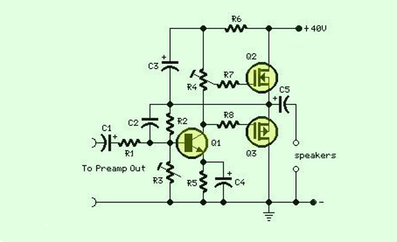
A differential input differential output amplifying circuit diagram
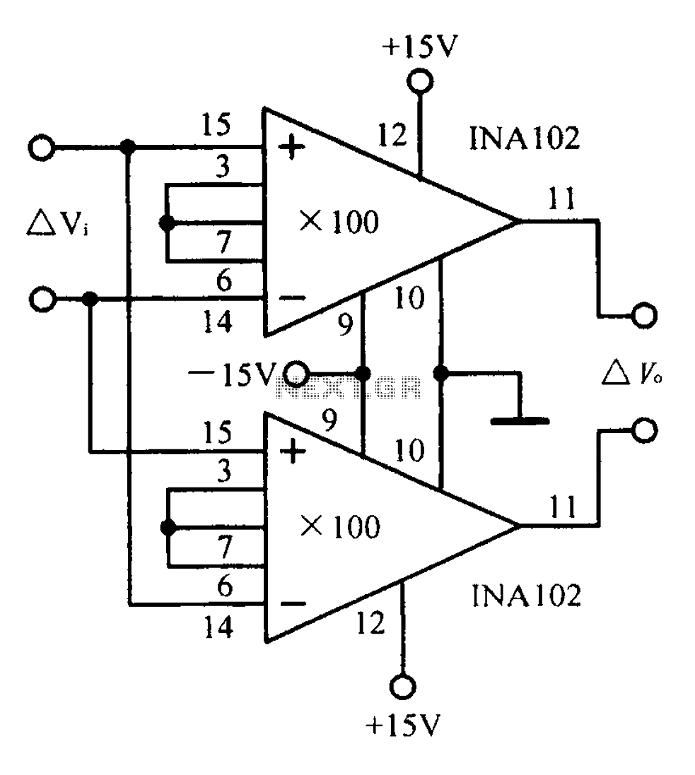
A differential input differential output (DIDO) amplifier is a type of operational amplifier configuration that is designed to amplify the difference between two input signals while rejecting any signals that are common to both inputs. This characteristic makes DIDO amplifiers particularly useful in applications where noise reduction and signal integrity are critical, such as in instrumentation and audio processing.
In a typical DIDO amplifier circuit, two input terminals (often labeled as V+ and V-) receive the differential signals. The output is taken from two output terminals, which provide the amplified difference. The circuit often employs resistors to set the gain, which can be adjusted by changing the resistor values. Feedback loops are commonly utilized to stabilize the gain and bandwidth of the amplifier, ensuring reliable performance over a range of frequencies.
The configuration may include additional components such as capacitors for frequency compensation, which helps to prevent oscillations and improve transient response. Power supply considerations are also important; the amplifier typically requires dual power supplies (positive and negative) to accommodate the full range of input signal variations.
Overall, the DIDO amplifier circuit is a versatile tool in electronic design, capable of delivering high precision and low distortion in various applications. Proper understanding of its design and implementation is essential for achieving optimal performance in specific use cases.A differential input differential output amplifying circuit diagram:
Related Circuits
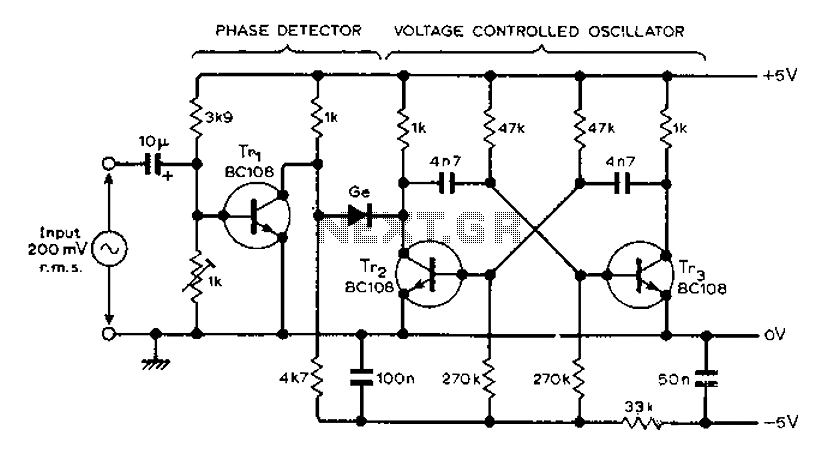
The circuit MVBR utilizes a traditional two-transistor configuration along with other components to create a simple phase-locked loop (PLL). The transistor TR1 and diodes function as a logic gate, activating during half periods of the input waveform of the...
NOTE: There is no guarantee as to the suitability of said circuits and information for any purpose whatsoever other than as a self-training aid. I.E. If it blows your equipments, trashes your hard disc, wipes your backup, burns your...
This PC fan controller circuit is designed with discrete components to control 12V fans that consume less than 200mA. The specified component values in the circuit diagram ensure that the voltage will not drop below 7V. If the fan...
The function of this circuit is an audio amplifier capable of delivering a decent output power with a minimal number of components, with considerable efficiency. This audio amplifier circuit is designed to enhance audio signals, providing sufficient output power while...
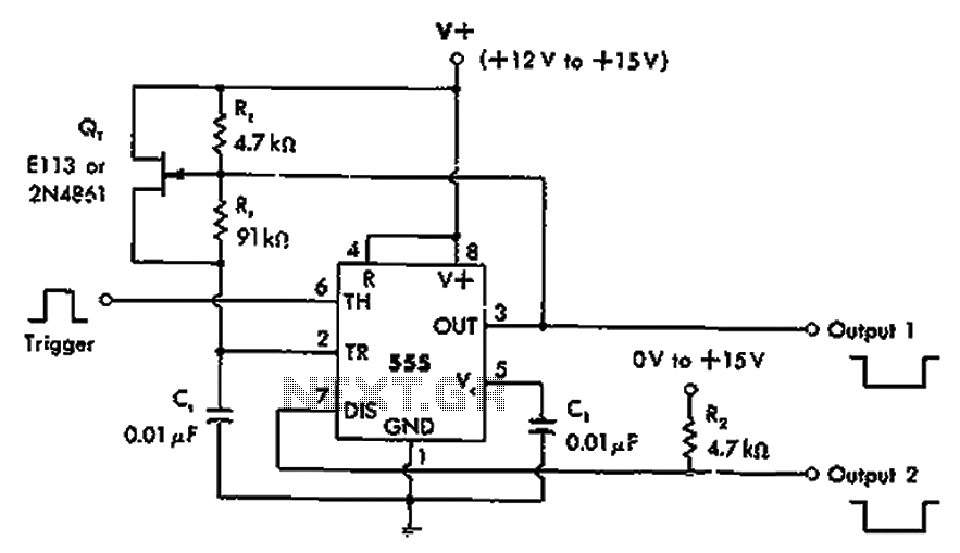
The timer 555 is activated by a positive trigger pulse, which results in negative output pulses. In scenarios where the duty cycle exceeds 99%, heavy loads can be disconnected from pin 7 without impacting timing accuracy, although loads exceeding...

This design outlines a high impedance DC voltmeter circuit utilizing the uA741 integrated circuit (IC). The uA741 is configured as a non-inverting DC amplifier. The circuit incorporates negative feedback through a DC meter that requires 1 mA for full-scale...
Warning: include(partials/cookie-banner.php): Failed to open stream: Permission denied in /var/www/html/nextgr/view-circuit.php on line 713
Warning: include(): Failed opening 'partials/cookie-banner.php' for inclusion (include_path='.:/usr/share/php') in /var/www/html/nextgr/view-circuit.php on line 713