
Hi-fi Audio Amplifier Circuit Design and implementation
The audio amplifier design employs discrete components to create a versatile and customizable circuit. The choice of a green standard LED for D1 is crucial, as it ensures a consistent voltage drop across the component, which is essential for maintaining circuit stability. The use of VR1 to adjust the quiescent current allows for fine-tuning of the amplifier's performance, enabling it to operate efficiently within the specified current range.
The transistors used in the design, particularly Q4, Q5, Q6, Q7, and Q8, are selected based on their thermal characteristics and current handling capabilities. Q4 acts as a driver stage, while Q5 and Q6 serve as output drivers that can handle moderate power levels without additional heat sinking. However, Q7 and Q8, which are likely the output transistors, require adequate heat dissipation mechanisms to prevent thermal failure during operation.
The design emphasizes the importance of ensuring that the output transistors' maximum collector current rating exceeds the expected load current. This consideration is vital for the longevity and reliability of the amplifier. The MJ15015 and MJ15016 transistors are commonly used in audio applications due to their robust performance characteristics, making them suitable for this amplifier design.
Overall, the schematic design of the audio amplifier reflects a careful balance of component selection and thermal management, allowing for an effective amplification of audio signals while accommodating various user requirements.Designing Audio amplifier from the scratch using discrete componentsis interesting, as it allow users to design amplifiers that can satisfy their various requirements. With audio amplifiers, low level sounds from mobile devices around us can be made more louder and lively as well.
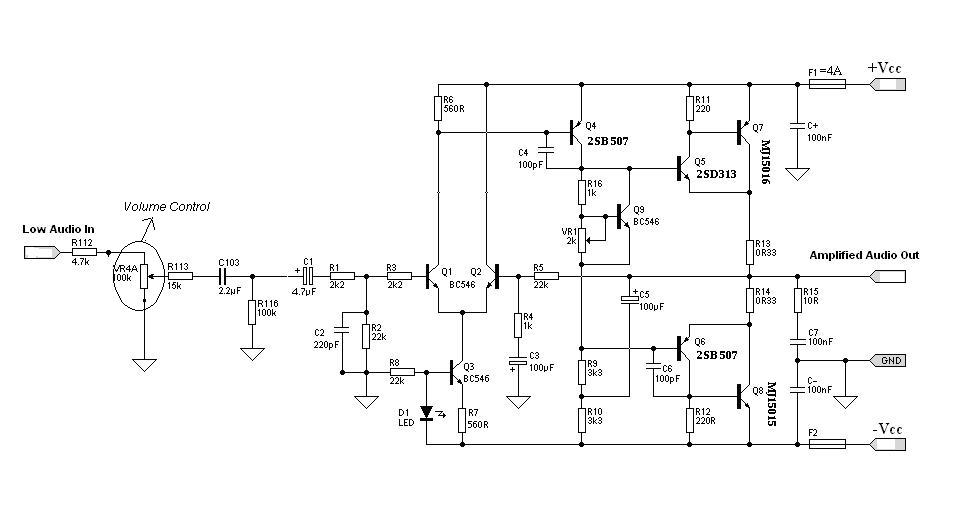
Based on the specifications of theHi-fi Audio amplifier, the values of the system components werecalculated and selected accordingly to give rise to the schematic shown in figure 1. 0. D1 is a green LED, and should be a standard type. Don`t use a high brightness LED, or change the colour. This is not for appearance (although the green LED looks pretty neat on the board), but for the voltage drop.
Different coloured LEDs have a slightly different voltage drop. VR1 is used to set the quiescent current, and normally this will be about 50-100mA. The amp will work happily at lower current, at less than around 40mA. Transistor Q4 and the output drivers (Q5 and Q6) will normally not require a heat sink. Q7 and Q8 seriously need a proper heat sink, else they will burn out! Note: Any specification can be chosen, but the modification on the circuit will affect the power supply used and the output transistors ( MJ15015, MJ15016 ). Make sure that the output transistor`s Maximum IC (Collector Current) is greater than the calculated IO.
You can get the detailed datasheet of all the components at Alldatasheet. com. 🔗 External reference
Related Circuits
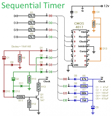
This timer is designed to generate a sequence of up to ten distinct events. Each event's duration can be set independently, and the sequence can be configured to run a predetermined number of times or continuously. Additionally, the individual...
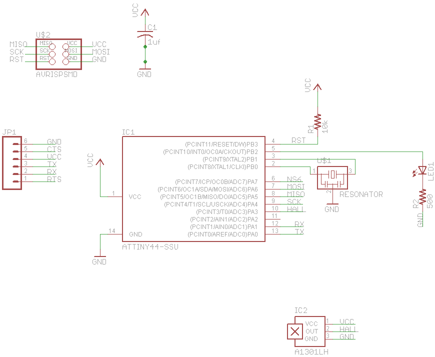
The final project involves cycling rollers that require a method to sense the rotational speed of one of the rollers. Speed sensors on bicycles typically function by detecting a magnet attached to a spoke on one of the wheels...
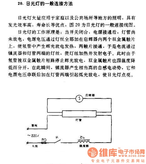
The general connection method for fluorescent lamps is utilized in residential and public lighting applications due to their luminous efficiency and long service life. The general wiring diagram for the lamp is illustrated in Figure 20. The working principle...
This DIY magnetic field sensor circuit is straightforward and capable of detecting both static magnetic fields and those that vary at audio frequencies. The unit is designed to be user-friendly and efficient. The magnetic field sensor circuit typically employs a...
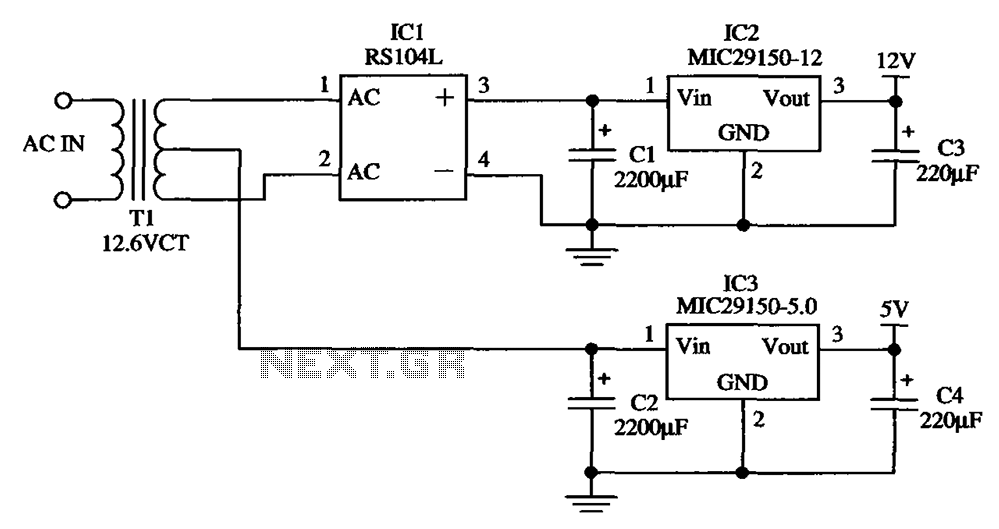
The low-cost dual output voltage regulator circuit is composed of two Micrel company regulators, the MIC29150-12 and the MIC29150-5.0. The dual output voltage regulator circuit utilizes the MIC29150 series from Micrel, which are low-dropout (LDO) voltage regulators designed for various...
With this counter you can count laps for example (in conjunction with the Simple light trap). The circuit uses two TTL ICs 74LSxx the series. The left IC is a decimaalteller. The input pulses 14 are counted and converted...
Warning: include(partials/cookie-banner.php): Failed to open stream: Permission denied in /var/www/html/nextgr/view-circuit.php on line 713
Warning: include(): Failed opening 'partials/cookie-banner.php' for inclusion (include_path='.:/usr/share/php') in /var/www/html/nextgr/view-circuit.php on line 713