
Digital counter circuit

The described circuit is a lap counter utilizing two TTL (Transistor-Transistor Logic) integrated circuits from the 74LS series. The first integrated circuit, designated as IC1 (74LS90), functions as a decimal counter. It is capable of counting input pulses, which in this application can be generated from various sources, such as a printer port. The maximum input voltage for the circuit is constrained to 5 volts to ensure compatibility with TTL logic levels.
The 74LS90 IC counts up to 10 (from 0 to 9) and outputs the count in Binary-Coded Decimal (BCD) format. This BCD output is then fed into the second integrated circuit, IC2 (74LS247), which serves as a BCD to 7-segment display decoder/driver. The primary role of the 74LS247 is to convert the BCD output from the 74LS90 into a format suitable for driving a common anode 7-segment LED display, designated as LD1.
Resistors R1 through R7, each valued at 220 ohms, are connected in series with the segments of the 7-segment display. These resistors limit the current flowing through the LEDs, thereby preventing damage and ensuring proper operation of the display. The common anode configuration of the display implies that the anode of each segment is connected to a positive voltage supply, while the cathodes are driven low by the 74LS247 to illuminate the respective segments.
Overall, this circuit provides a straightforward solution for counting laps or similar applications, effectively utilizing TTL technology to achieve reliable performance in pulse counting and display driving.With this counter you can count laps for example (in conjunction with the Simple light trap ). The circuit uses two TTL ICs 74LSxx the series. The left IC is a decimaalteller. The input pulses 14 are counted and converted to the corresponding BCD code. This code is passed to the second IC, which is a code converter and display driver. Here the BCD code correct the display driver for LD1. The counter can be any TTL signal is sent (eg with the printer port). The signal must not exceed 5 volts. R1-R7 = 220 ? LD1 = 7 segment LED display (common anode) IC1 = 74LS90 IC2 = 74LS247 🔗 External reference
Related Circuits
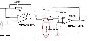
Can someone explain why there is an LC filter in the op-amp circuit? Additionally, are there any modifications that can be made to enhance the sound quality? The presence of an LC filter in an operational amplifier (op-amp) circuit serves...

This circuit provides protection for telephones, EPABX systems, telephone modems, and similar devices against lightning discharges and line voltage spikes. It incorporates a safety capacitor and gas discharge components. The circuit employs a safety capacitor to filter out high-frequency noise...
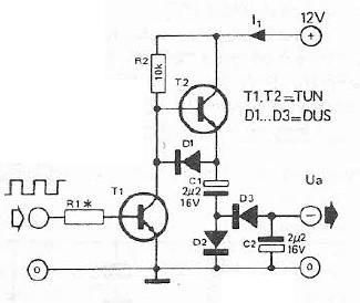
Voltage inverter circuit design electronic project using few electronic components The voltage inverter circuit is a fundamental electronic project that converts direct current (DC) to alternating current (AC). This circuit is particularly useful in applications where AC voltage is required...
This simple and inexpensive circuit built around a popular CMOS hex inverter IC CD4069UB offers four sequential switching outputs that may be used to control 200 LEDs (50 LEDs per channel), driven directly from mains supply. Input supply of...
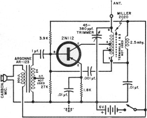
It had been a little over a decade since the invention of the transistor when this article appeared in the August 1959 edition of Popular Electronics. Transistors were still a mystery to many, including engineers, technicians, and hobbyists. Author...
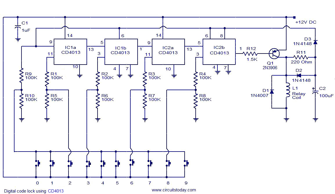
This is a simple yet effective code lock circuit featuring an automatic reset function. The circuit is built around the dual flip-flop integrated circuit (IC) CD4013, utilizing two CD4013 ICs. Push button switches are employed for entering the code....