
Hi-Fi DX Bass circuit
The passive DX bass circuit operates by manipulating audio signals to enhance the bass response while maintaining a balanced output across the frequency spectrum. The circuit consists of two main stages: the tone control stage and the compression stage.
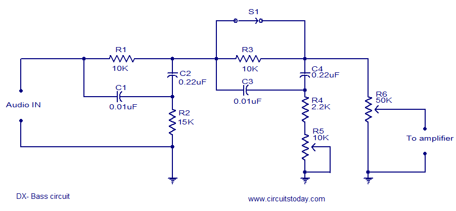
In the tone control stage, the 0.01 µF capacitor is strategically placed to filter out high-frequency signals, allowing the lower frequencies to be amplified and balanced with the treble. The 0.22 µF capacitor serves a similar purpose for low frequencies, ensuring that the bass response is pronounced without overwhelming the overall sound quality. This stage is crucial for achieving a desirable sound profile, especially when paired with various audio amplifiers.
The second stage focuses on sound compression, which is essential for managing audio dynamics. The capacitors in this stage are tasked with initiating the compression process, which helps to prevent distortion and maintain clarity at higher volumes. The introduction of the 2.2 kΩ resistor plays a significant role in delaying the sound, effectively multiplying the compression effect. This delay can enhance the perceived richness of the bass, making it more impactful during playback.
The 10 kΩ variable resistor provides flexibility in tuning the circuit to suit different speaker configurations. Adjusting this resistor allows users to optimize the circuit's performance based on the specific frequency response of their speakers. For smaller hi-fi speakers, setting the resistor to 0 ohms minimizes the compression effect, allowing for a more natural sound reproduction.
Overall, the passive DX bass circuit is versatile and user-friendly, making it suitable for a wide range of audio applications. Its design encourages experimentation and adaptation, empowering users to modify the circuit to meet their individual preferences while ensuring high-quality audio output.Here is the circuit diagram of a passive DX bass circuit that can be used with almost all audio amplifiers. This circuit is designed by Mr. Emmanuel Chipula ( emmanuel@windowshoppingmalawi. com ) from Malawi and was sent to us for publication. We tested this circuit in our lab and the result was fine. Full credit of this circuit goes to Mr. Emmanuel C hipula and we thank him for his contribution. Emmanuel`s comments on the circuit : The circuit that I have designed is a passive one but you can make it an active one by adding a pre amp at the output. The first stage acts as a main tone stage. It balances the bass and the treble. The 0. 01 cap is for high frequency while the 0. 22uF cap is for low frequency. The second stage is for sound compression. the caps works the same as at the first stage only that they are there to start the sound compression that is received from the input stage.
The 2. 2k resistor delays the sound thereby multiplying the compression. The 10k variable resistor is there used to tune the compression depending on the frequency of the speaker. If you are using 4 to 6 inches hi-fi speakers, I advise you to keep the 10k variable resistor at 0 ohm.
The circuit is not copyrighted and you can change it to suit your requirement. All I ask is to be posting the updates of the circuit design on the site. 🔗 External reference
Related Circuits
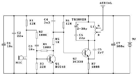
The tuned coil L1 has two output tap points for the antenna connection, labeled "A" and "B." Both outputs are low-level, allowing the user to select between a stable low range or a more unstable but higher range. Tap...
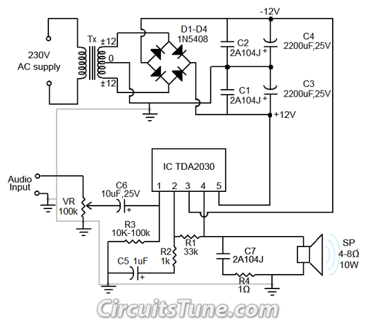
All ground points in the circuit should be connected to a single point and grounded if possible, or connected to the transformer's 0V marked wire as shown in the circuit. In electronic circuit design, proper grounding is crucial for maintaining...
The controller for the Hybrid Power Plant (HPP) is represented in a block diagram format. It consists of 440 Wp photovoltaic modules, a 1 kW wind turbine, and a 5 kW diesel engine as a backup power source. The...
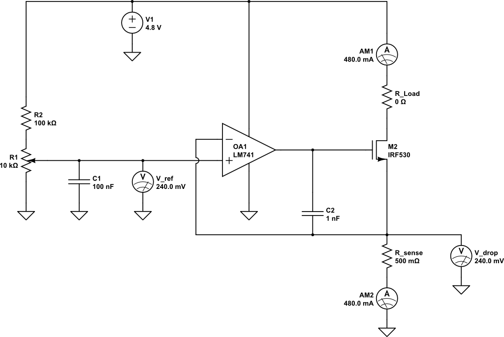
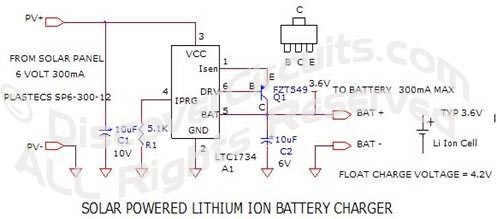
A current limiting circuit is designed to select a maximum current through a load, set to a maximum of 480 mA. As the load resistance increases, the series equivalent resistance (SER) of the limiting circuit decreases. When charging a...
This is a simple transistor tester circuit that can be utilized to test both NPN and PNP transistors. The voltage source consists of a 6V power supply, which is derived from a step-down transformer that converts 230V AC to...
The following circuit illustrates the AD8531 integrated circuit used for the automatic control of LCD panel backlighting. Features include the ability to compensate for aging effects and other functionalities. The AD8531 is a precision operational amplifier known for its low...