
Hi-Fi Microphone Preamplifier circuit
The preamplifier achieves frequency response equalization according to the Recording Industry Association of America (RIAA) standards. Another layer of equalization is provided by utilizing the de-emphasis curve as per the International Electrotechnical Commission (IEC) guidelines.
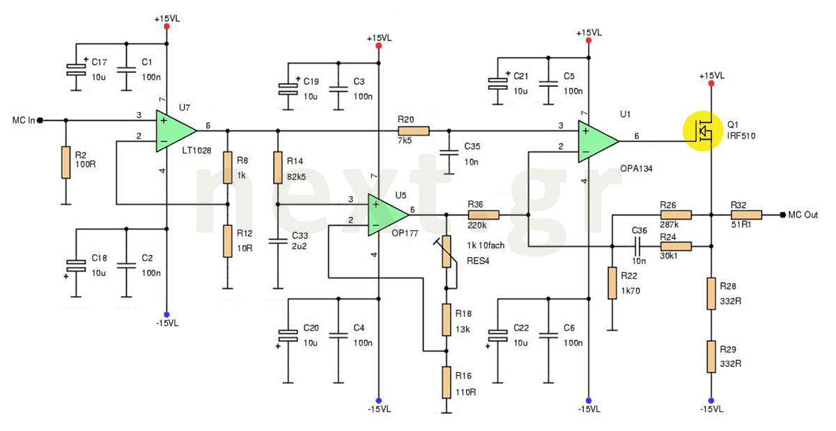
The preamplifier comprises several interconnected stages, as illustrated in the circuit diagram. The key components include:
1. An ultra-linear low noise amplifier offering 40 dB of amplification.
2. A low-pass filter with a cut-off frequency of 2122 Hz.
3. A second amplification stage that functions as an active filter.
4. An offset compensation circuit that limits the DC component of the signal from the first amplification stage.
The preamplifier utilizes integrated circuits such as the LT1028, OPA177, and OPA134, with the MOSFET transistor being the IRF510. At least two amplification stages are necessary, as a single booster cannot achieve a 64 dB gain at 1 kHz (84 dB at 20 Hz) while maintaining high quality. A single stage would yield a large total distortion factor due to insufficient signal-to-noise gain to compensate for inherent nonlinearities.
To achieve the RIAA equalization curve, two separate filters are designed instead of a composite filter. Constructing a three-pole filter is challenging when the poles in the Bode diagram are close together, as this can affect the performance of the other poles. Consequently, low frequencies are amplified while high frequencies are attenuated, focusing primarily on audio frequencies relevant to human speech.
The preamplifier circuit begins with the first amplification stage, where an irreversible amplifier boosts the input signals to match the output. This low-frequency amplifier can amplify frequencies below the acoustic spectrum and also boost DC signals, which is advantageous for power amplifiers. Notably, there is no capacitor at the input of the incoming currents, allowing both AC and DC signals to pass.
The passive low-pass filter follows the initial amplification. This filter allows low-frequency signals to pass while attenuating signals above the cut-off frequency. A passive filter is defined as one whose output relies solely on the input and the circuit's characteristics, such as resistance or capacitance. The low-pass filter is constructed using a resistor-capacitor (RC) configuration, where a high-quality styroflex capacitor with a tolerance of 1% is recommended, with a maximum value of approximately 15nF.
The second amplification stage also acts as an active filter. While a passive filter could be implemented here, it would not be effective due to the need for further signal enhancement. An active filter requires an external power source (DC supply) to amplify the signal. This is accomplished by incorporating a series combination of a resistor and capacitor in the feedback loop of the amplifier.
At low frequencies, the capacitor's impedance is high, making the gain dependent on the resistor. At high frequencies, the capacitor behaves like a short circuit, and the gain is determined by the parallel combination of resistors. The circuit includes a Class A output stage using a power MOSFET, with DC compensation occurring in the first stage to ensure only the second stage's amplification is present at the output. A passive low-pass filter is formed using a resistor and capacitor in this configuration.
The preamplifier is powered by a 220V AC supply, which is transformed to 12V AC. Voltage regulators LM7812 and LM7912 stabilize the output voltage at 12V. It is crucial to ground the transformer and any metal parts of the enclosure to ensure safety through double isolation in external power supplies. The diodes used in the circuit should be of type 1N4002 or similar, capable of withstanding a 100V reverse voltage and a current of 1A. Voltage regulators do not require heat sinks due to low current consumption, approximately 26 mA.
Diodes are included around the voltage regulators to prevent reverse currents that could damage the integrated circuits. While not strictly necessary, they are a prudent addition. Capacitors of 100nF should be placed close to the power supply of the integrated circuits to minimize voltage fluctuations.This microphone preamplifier circuit strengthens the acoustic signal of a mobile coil microphone or MC (Moving Coil) with a sensitivity of 150μV at the line level. In this construction this technique is not used because the noise produced is not important to affect the end result.
The sequence of the electronic data link, used to drive the audio signal, makes the whole device capable of handling all the signals generated by the MC microphone. Usually there is a high-pass filter somewhere in the chain between the output and the speaker, which has high levels of sub-bass cut-off.
The preamplifier achieves the frequency response equalization according to the Recording Industry Association of America (RIAA). Another equalizer is given by using the de-emphasis curve, according to the International Electro technical Commission (IEC).
The preamplifier consists of several steps in adaption to each other.
All this is shown in the circuit shown in the drawing.
- 1. an ultra-linear low noise amplifier that offers amplification at 40 dB,
- 2. a low-pass filter or low pass filter with a cut-off frequency of 2122 Hz,
- 3. a second reinforcement step which acts as an active filter and, finally,
- 4. by an offset compensation circuit which limits the DC component of the signal coming from the first amplifier stage.
The preamplifier use the chips LT1028, OPA177 and OPA134. The MOSFET transistor is the IRF510. At least two booster steps must be used because a boost of 64 dB at a frequency of 1 kHz (84 dB at 20 Hz) can not only handle a booster step and deliver high quality.
The total deformation factor by harmonic components will be large because a single gradient does not have enough signal-to-noise gain to compensate for inherent nonlinearities.
Two separate filters were designed instead of a composite filter to achieve the RIAA equalization curve. It is very difficult to construct a three poles filter when the poles in the Bode diagram are very close, thus affecting one pole others.
That is why the low ones are amplified and the high frequencies are cut, since they are audio frequencies and mainly for human speech frequencies.
The preamplifier circuit starts with the first boost step. The irreversible amplifier amplifies the signals in such a way that the output signals are in line with the input signals.
This is due to its connection. This low-frequency amplifier not only has the ability to amplify frequencies below the acoustic spectrum but also boosts DC, another bigger advantage of power amplifiers. As we can see in the electronic circuit, there is no capacitor at the input of the incoming currents.
Such a capacitor, in other applications, allows only the alternating signals to pass.
The passive low pass filter
After the first amplification step, the signal must be led to the passive low pass filter. It is a filter that lets you pass low-frequency signals and mitigates (reduces their amplitude) signals at frequencies higher than the cut-off frequency.
What is a passive filter?
Suppose we have a circuit. If its output depends only on the input and the characteristic constant values ​​of the element (eg resistor) or the circuit (eg voltage divider) or the system (eg. optical fiber) and from nothing else, then the element, circuit or system is passive. The passive low pass filter consists of a simple RC resistor/capacitor.
The capacitor must be of very good quality.
The only option is to be a styroflex capacitor, available at a tolerance of 1%. Its highest value is about 15nF.
The second boost step also serves in the circuit as an active filter. A passive filter could also be used here, but this will not make sense because the signal should be further enhanced.
Any reinforcement, however, would increase distortion, which is not desirable at all. What is, however, an active filter? Suppose we have a signal and we want to create a larger signal than we have.
Then the medium with which the largest signal is generated is active. Obviously, it needs another signal (DC power supply) to be able to do this. One such instrument, which can do this job, is an amplifier. Any circuit has a DC supply is designated as active and any circuit can have amplifier then it is active.
Therefore, an active filter is needed where amplification will give a constant DC signal. This is easily accomplished by placing a series combination of R24 resistor and capacitor C36 in parallel with resistor R26 in the feedback loop.
At very low frequencies the impedance of C36 is very high and so the boost depends only on R26. At very high frequencies the impedance of C36 is almost equal to a short circuit and thus the amplification is dependent on the parallel combination of resistors R26 and R24.
Then follows an output class A in the feedback loop using a power MOSFET.
The Q1, therefore, MOSFET power is connected as a source source using the resistors connected to source R28 and R29. DC compensation also occurs in the first step so that only the amplification from the second stage is shown at the output of the preamplifier. Thus, resistance R14 and capacitor C33 are connected, forming a passive low pass filter.
The Power Supply
The pre-amplifier is powered by the 220V network.
From then on, there is a transformer at 12 V AC. Here are the voltage regulators or voltage regulators 7812 and 7912, respectively. Thus, the stabilized voltage output is at 12 V. Never forget to ground the metal parts of the transformer as well as any metal part of the box that encloses it. If this is not the case, then the following disadvantage arises: there will not be the correct security marker created by the double isolation that is needed in external power packs.

All diodes must be of type 1N4002 or the like.
The main feature of these diodes is that they withstand a 100 V reverse voltage and a current passing through them at 1A. Voltage regulators do not need heat sinks, the so-called brushes, because the total current consumption is around 26 mA.
There are some diodes around the voltage regulators in the power supply circuit.
The reason for their existence is to prevent the occurrence and development of backward tendencies in the regulators and under any condition. This would be detrimental to these integrated circuits. Of course, they are not absolutely necessary, but they are good. Capacitors of 100 nF must be close to the power supply of the integrated ones. This prevents the occurrence of vibrations.
Related Circuits
JG series of photoelectric relay circuit. To ensure reliable operation, a Schmitt trigger circuit has been incorporated. These circuits function similarly; when light strikes the photosensitive component, its internal resistance decreases, activating the transistor VT and subsequently energizing the...
This is a simple portable audio amplifier circuit. The circuit is built around the TEA2025 integrated circuit, which is a monolithic audio amplifier housed in a 16-pin dual in-line package manufactured by UTC. The circuit features an internal thermal...
The LEDs in the circuit light up sequentially and "dance" in response to the music level applied at the input, preferably from the speaker terminals of the audio device being monitored. This configuration is consistent across all LEDs in...
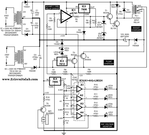
This circuit illustrates the use of the 7806 IC in an automatic battery charger circuit diagram. It is designed for a car battery with an approximate rating of 40 Ah. The automatic battery charger circuit utilizing the 7806 integrated circuit...
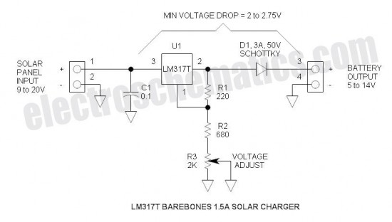
This is the simplest and most affordable solar battery charger that a hobbyist can create. It has some drawbacks compared to other similar controls, but offers unique advantages. The solar battery charger circuit is designed to harness solar energy to...

This shadow alarm circuit can detect a moving shadow in a confined area, providing protection against theft. When an individual approaches the unit, it triggers a loud alarm to deter the theft attempt. The circuit leverages the light-sensing characteristics...
Warning: include(partials/cookie-banner.php): Failed to open stream: Permission denied in /var/www/html/nextgr/view-circuit.php on line 713
Warning: include(): Failed opening 'partials/cookie-banner.php' for inclusion (include_path='.:/usr/share/php') in /var/www/html/nextgr/view-circuit.php on line 713