
led music level indicator light circuit
In this circuit, the sequential LED display serves as a visual representation of audio input levels, effectively transforming sound energy into light energy. The PNP transistor at the input stage plays a crucial role by amplifying the low-level audio signal extracted from the speaker terminals. This amplification is essential, as it ensures that even subtle variations in music volume can be detected and represented visually by the LEDs.
The arrangement of diodes in the circuit introduces a series voltage drop that affects the conduction threshold of each subsequent transistor. By limiting the current flow through each transistor with the diodes, the circuit creates a cascading effect where each LED lights up in response to increasing audio levels. This behavior mimics the dynamic nature of music, where changes in pitch and loudness are represented by the sequential illumination of the LEDs.
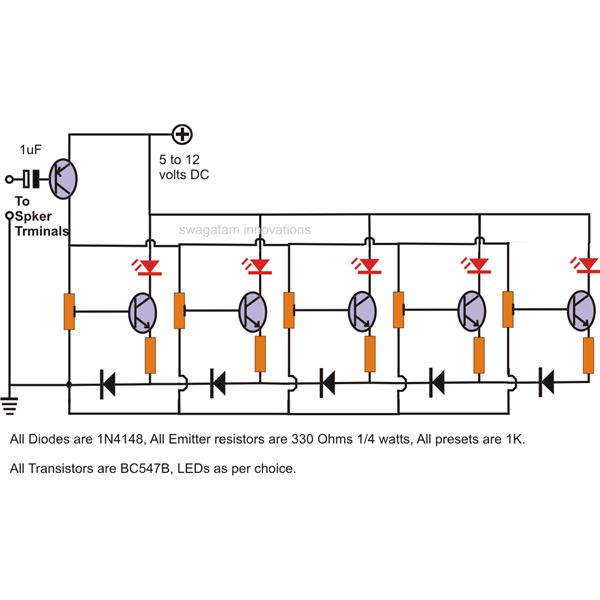
The design is particularly effective for visualizing audio signals, as it allows for immediate feedback in response to changes in the music. As the audio input varies, the circuit responds by illuminating the LEDs in a manner that reflects the intensity and frequency of the sound, thus creating an engaging visual display. The overall configuration not only enhances the aesthetic appeal of audio devices but also provides users with an intuitive understanding of audio levels through visual feedback.The shown LEDs in the circuit sequentially light and "dance" as per the level of the music applied at the input, preferable directly from the speaker terminals of the audio gadgetwhosemusic level is to be monitored. The above stage is identical to all the LEDs included in the circuit for obtaining the desired push-pull effect in response to th
e applied music level at the input. If you see the circuit closely you will find that the the ground to the first transistor/LED stage from left comes across only a single diode, however the preceding stages ground potential has to encounter the extracorrespondingnumber of diodes in theor path. As we allknowthat a diode has thepropertyof dropping 0. 6 volts, means that the first transistor would conduct much sooner than the second, the second transistor conducts sooner than the third and so on.
Because as the number of diodes increase in the path of therespectivetransistor, the conduction is inhibited until the the voltage sufficiently increases for bypassing the diodes overall forward voltage. This increase in voltage can happen only when the pitch of the music increases, giving rise to a sequentially running LED bar graph which shoots forward in response to the pitch or loudness o the applied input music.
The transistor at the inputisa PNP and complements the rest of the transistors employed forilluminatingthe LEDs. The PNP transistor at the input amplifies the applied low level music sinal to levels which is just enough for illuminating the LEDs with reference to themusiclevels, .
🔗 External reference
Related Circuits
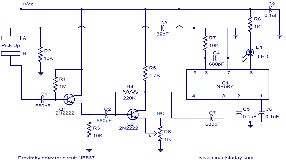
A simple proximity detector circuit utilizing the NE567 integrated circuit (IC). The circuit activates an LED when an object approaches the sensor. The NE567 is a versatile phase-locked loop (PLL) device commonly used for applications such as proximity detection due...
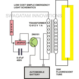
This simple home emergency light circuit utilizes very few components while still being capable of producing a reasonable amount of illumination. The components used are common and can be easily sourced from local electronic retailers. The oscillations induce an...
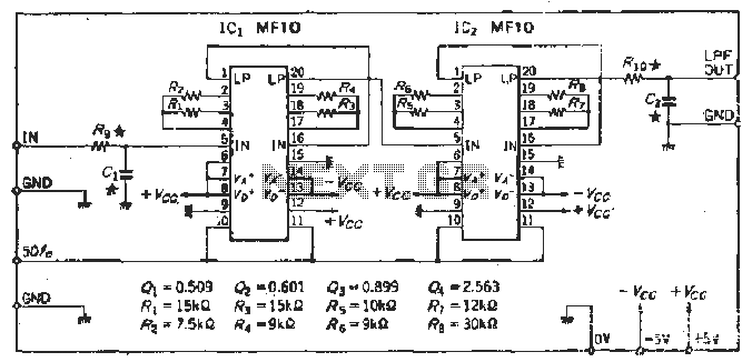
To create a Butterworth low-pass filter with a 12 dB/octave roll-off, four second-order (12 dB/oct) filter blocks are connected in series. This configuration is intended to achieve flat response characteristics across the frequency spectrum. The values for each stage...
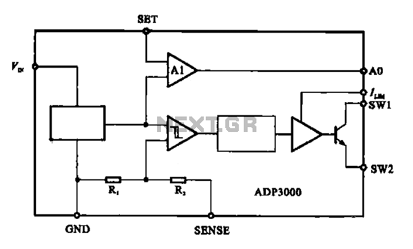
The ADP3000 is an integrated circuit featuring a block diagram that illustrates its internal structure as a high-frequency switching regulator. The ADP3000 integrated circuit is designed to provide efficient power management in various applications, particularly in systems requiring high-frequency switching...

This circuit turns off an amplifier or any other device when a low-level audio signal fed to its input is absent for at least 15 minutes. By pressing P1, the device is powered on, supplying power to any appliance...
This is the circuit diagram of a line follower/line tracker robot. The circuit is derived from tutorial documentation, which can be downloaded at the end of this article. The line follower robot utilizes eight proximity sensor modules. Each sensor...