
Hi-lo temperature sensor
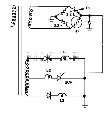
The described circuit utilizes a bridge configuration comprising resistors R1, R2, and two additional 2.2 kΩ resistors. In this setup, R2 functions as a thermistor, which is a temperature-dependent resistor. The resistance of R2 varies with temperature, allowing it to serve as a sensing element in the circuit. R1 is configured to establish a reference temperature threshold, which dictates when indicator LED L2 will illuminate.
The bridge circuit operates on the principle of balancing the resistances. When the temperature sensed by the thermistor R2 deviates from the set point defined by R1, the balance of the bridge is disturbed. This imbalance results in a voltage change at the output of the bridge circuit, triggering the appropriate response from the indicator LEDs. Specifically, if the temperature exceeds the designated threshold, LED L1 will light up, signaling an over-temperature condition. Conversely, if the temperature falls below the threshold, LED L3 will illuminate, indicating an under-temperature condition.
The use of a thermistor in this application is critical due to its sensitivity to temperature changes, allowing for precise monitoring and indication of temperature variations. The two 2.2 kΩ resistors are likely employed to complete the bridge and ensure that the circuit remains stable across a range of operating conditions. The overall design is effective for applications requiring temperature monitoring and alerting, providing visual cues for temperature management.Resistors Rl, R2, and the two 2.2 k resistors form a bridge circuit. R2 is a thermistor, and Rl sets the temperature at which L2 lights. Lower or higher temperatures light LI or L3 to indicate an over- or under-temperature condition. 🔗 External reference
Related Circuits
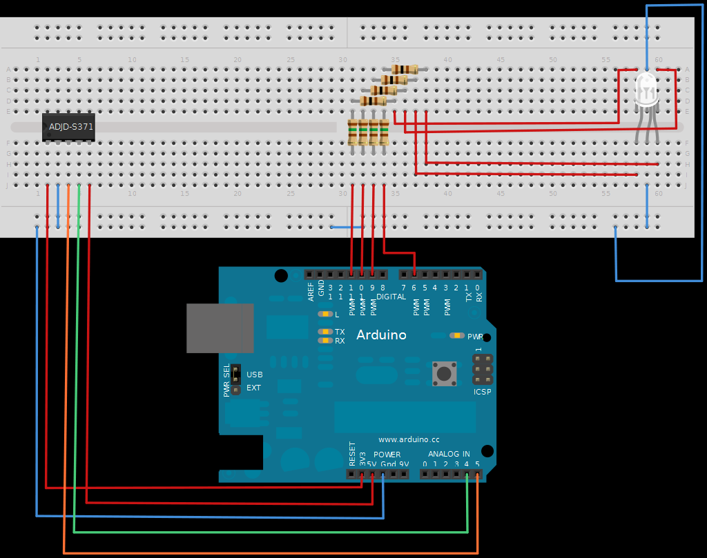
The next board presented is the ADJD-S371 Color Light Sensor Evaluation Board from SparkFun. This board emits light and analyzes the reflected color spectrum. It can be controlled via I2C, while the sleep and xclk pins were not utilized...
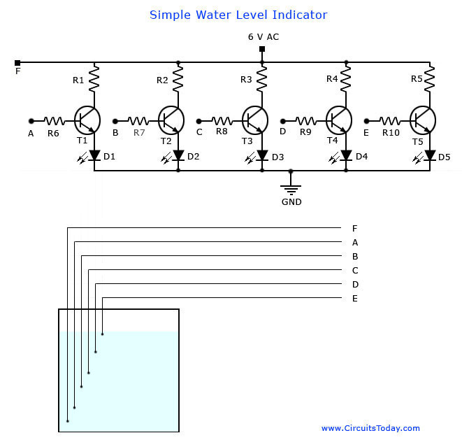
A simple water level indicator project with a circuit diagram for home and industry. This water tank level sensor can be utilized for any liquid level indicator projects. The water level indicator circuit is designed to monitor and display the...
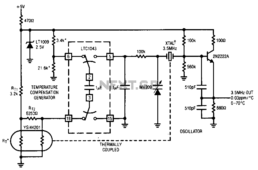
This circuit employs the LTC1043 to distinguish between a temperature sensing network and a de reference. The single-ended output biases a varactor-tuned crystal oscillator to compensate for drift. The varactor crystal network exhibits high de impedance, negating the necessity...
R1 = 470K, N1, N2 = MC14093B, R2 = 15M, T1 = 2N3906 (also compatible: PN200, 2N4413), C1-C4 = 2.2nF (NTE159, ECG159, BC557, BC157, TUP), D1 = 1N4001, Ry = Relay (12V or matching supply voltage), D2, D3 =...
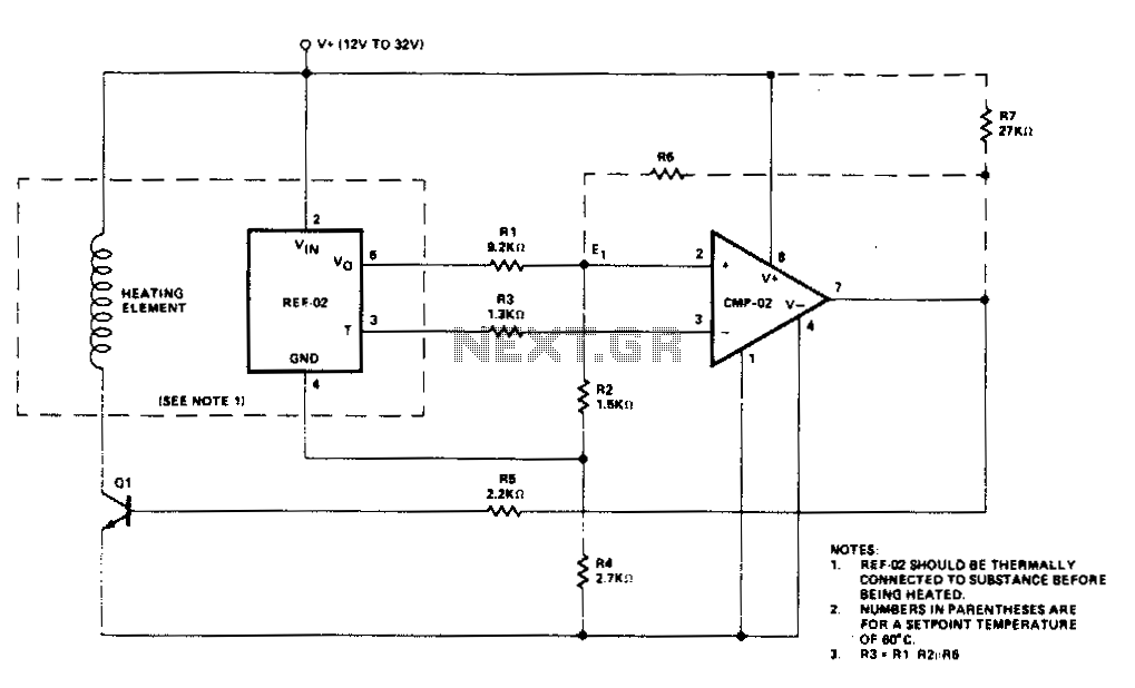
Temperature control is accomplished using the REF-02 +5 V Reference/Thermometer in conjunction with the CMP-02 Precision Low Input Current Comparator. The CMP-02 activates a heating element driver (Q1) whenever the current temperature falls below a predetermined setpoint, which is...
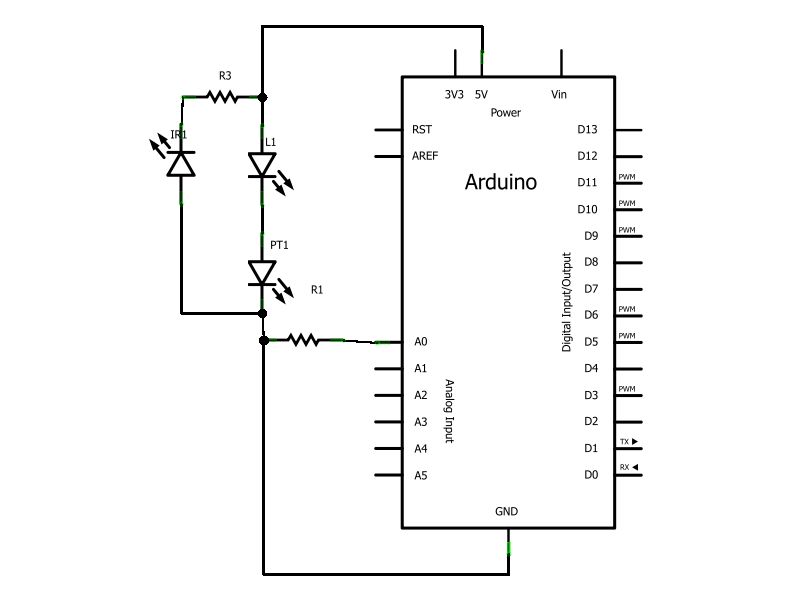
Have you ever wanted to create a line-following robot but found infrared sensors too expensive? If you are located in the UK and have access to a Maplin store nearby, you can purchase infrared transmitters and receivers for just...