
rgb color sensor on arduino
The ADJD-S371 Color Light Sensor Evaluation Board is designed to provide a comprehensive solution for detecting and analyzing color within the visible spectrum. It features a compact design that includes a light-emitting diode (LED) and a photodetector, enabling it to measure the intensity of reflected light across various wavelengths. The I2C interface facilitates straightforward integration with microcontrollers, allowing for efficient data communication and control.
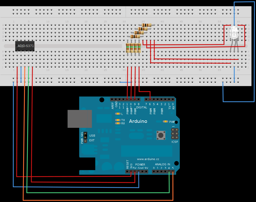
In the context of an Arduino setup, the board can be connected using the I2C protocol, which requires only two wires: SDA (data line) and SCL (clock line). This minimizes the complexity of wiring, making it suitable for prototyping and educational purposes. The sleep and xclk pins, while present on the board, are not necessary for basic operation in this example, allowing users to focus on the core functionality of color detection.
The RGB LED utilized in this setup enhances the capability of the project by providing visual feedback corresponding to the detected colors. The configuration of the LED with six pins enables independent control over each color channel, allowing for a wide range of color mixing and display options. The additional schematic used in this project likely accommodates the specific requirements of the RGB LED, ensuring proper current limiting and voltage levels.
Fritzing software plays a crucial role in the design and documentation of the circuit. Its user-friendly interface allows for the easy creation of protoboard layouts, circuit diagrams, and PCB designs, facilitating a seamless transition from concept to physical prototype. This capability is particularly valuable for engineers and hobbyists alike, streamlining the design process and enhancing the overall efficiency of project development. The availability of tutorials and community resources further supports users in leveraging the full potential of the ADJD-S371 sensor and associated components.The next board I want to show you is the ADJD-S371 Color Light Sensor Evaluation Board from sparkfun. It emits light and analyses the reflected color spectrum. The board can be controlled via I2C. The sleep and xclk pins were not used in this example. I found a really nice tutorial describing how to connect the sensor to the Arduino. The example also provided the code to communicate with the sensor. I only had to change minor parts to fit my needs. My basic setup looks a little bit different because I used a full color rgb LED with six pins. Two for ground, one for red, one for green and two for blue. I also used another schematic this time. What you see here is a software developed by the University of Applied Sciences Potsdam, here in Germany. The software is called Fritzing. You can design your circuit on a protoboard, convert it into a circuit diagram and even into a PCB layout for later manufacturing.
It`s really nice and easy to use. Thanks for the tip Darsh! 🔗 External reference
Related Circuits
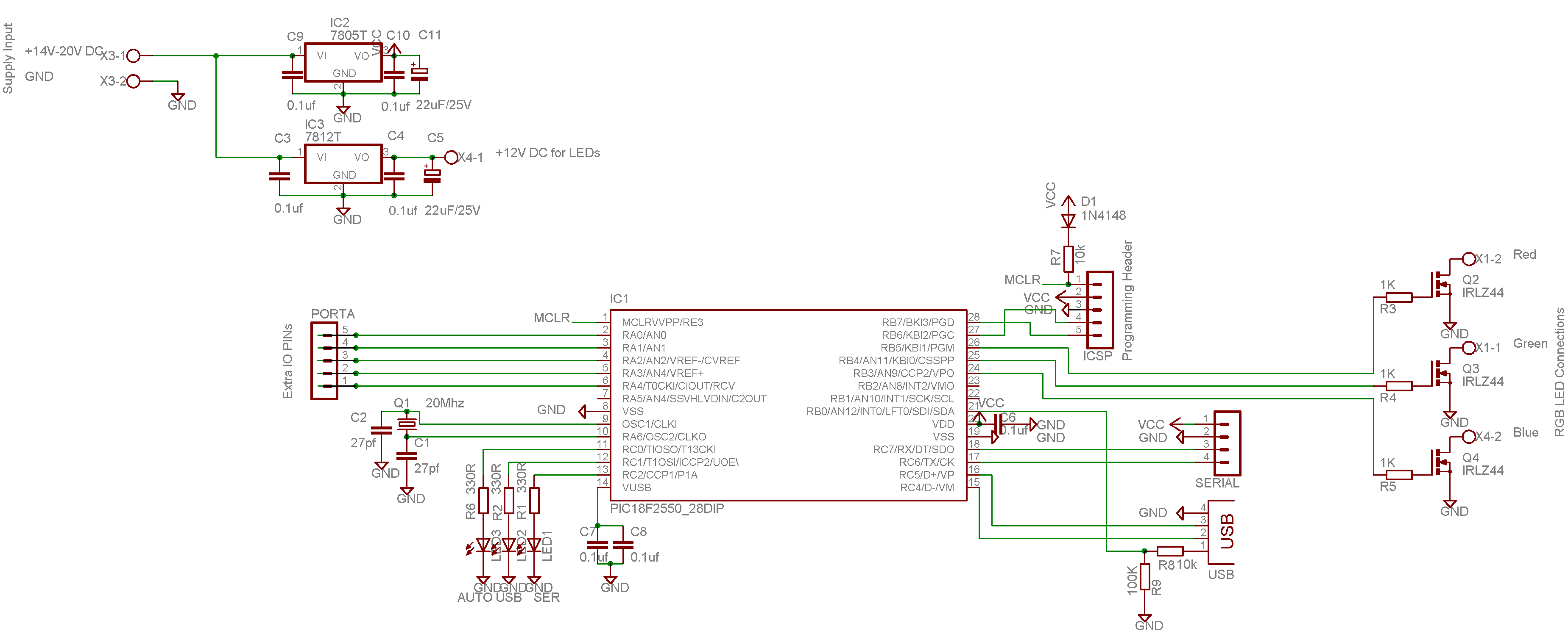
This color changer mixes light from high-power LEDs to create over 16 million colors. A smooth auto-fader cycles the colors, or it can be connected to a USB port for computer control. The device utilizes a well-known color model...
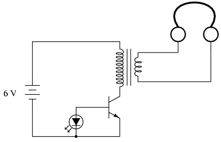
If you do not have an audio detector already constructed, a set of closed-cup audio headphones that completely cover the ears, along with a 120V/6V step-down transformer, can be utilized to create a sensitive audio detector for this experiment....
This line-following robot sensor, also known as a surface scanner for robots, is a compact, stamp-sized infrared proximity detector designed for short-range detection (5-10 mm). It is built around a standard reflective opto-sensor, the CNY70 (IC1). In various applications,...

Arduino is an open-source electronics prototyping platform that features flexible and user-friendly hardware and software. It is designed for artists, designers, hobbyists, and anyone interested in creating interactive objects or environments. Arduino can sense the environment by receiving input...
This is a hot water level indicator circuit. This circuit can be used to monitor the level of hot water in a tank. It is simple and inexpensive. The hot water level indicator circuit is designed to provide a reliable...
The metal detector circuit is presented here, illustrating a simple yet effective design. It utilizes a 40, 106 Hex Schmitt inverter IC, a capacitor, a search coil, and batteries. An advantage of connecting IC1b Pin 4 to a medium-wave...