
High-Frequency Oscillators
The Golpitts circuit and the coupled-grid self-excited oscillator circuit are essential for generating high-frequency signals in industrial applications, particularly in induction heating systems. The design allows for efficient voltage transformation and rectification, which is critical for high-voltage applications.
In the Golpitts circuit, the use of capacitors C2 and C3 in conjunction with the inductance L creates a resonant condition that maximizes the output power at the desired frequency. The careful selection of the inductance tap ensures that the circuit remains tuned, even when different heating coils are introduced, which is vital for maintaining performance consistency.
The blocking capacitor C4 plays a crucial role in isolating the resonant circuit from direct current, thereby ensuring that only alternating currents contribute to the heating process. This isolation is necessary to prevent damage to the oscillator tube and maintain stable operation.
The high-frequency choke coil is designed to allow direct current to pass while blocking high-frequency signals, effectively protecting the rectifier from potential feedback that could disrupt its operation. The feedback mechanism involving capacitor C3 is integral to the self-regenerative nature of the oscillator tube, allowing it to amplify the signal and sustain oscillations without external input.
In the coupled-grid self-excited oscillator circuit, the feedback coil's inductive coupling to the variable inductance L provides a means of fine-tuning the oscillator's frequency response, allowing for adjustments based on the specific requirements of the application. This adaptability is essential in industrial settings where different heating requirements may arise.
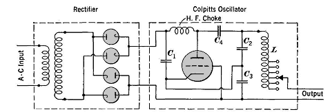
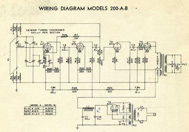
Overall, both circuits exemplify advanced techniques in high-frequency signal generation and rectification, showcasing the intricate balance of components that enable efficient operation in demanding industrial environments.High frequencies are here defined as those above 50, 000 cycles per second. For industrial power supply the Golpitts circuit, Fig. 28-1, or the coupled-grid self-excited oscillator circuit, Fig. 28-2, is most commonly used. In either circuit, the alternating supply voltage is stepped up through a power transformer to some voltage between about 7500 and 15, 000 volts and is then rectified by a suitable bank of mercury -vapor rectifier tubes. In Fig. 28-1 the condensers C2 and C3 form an anti-resonant circuit with L and the inductance of the load which may be an induction heating coil fed at the output terminals. The inductance L is tapped so that, even though different heating coils may be used, the total inductance of the circuit can be kept at proper value for anti-resonance at the desired frequency.
Condenser C4 is a "blocking" condenser and prevents the flow of direct current into the resonant circuit. The high-frequency choke coil passes the direct current to the anode of the oscillator tube, but presents a high limiting impedance to the high-frequency currents which would otherwise flow back into the rectifier.
The condenser C1 by-passes back to the cathode any high-frequency current which does pass through the choke. The voltage across condenser C3, being applied between the grid and the cathode of the oscillator tube, feeds back part of the tube`s anode output, and so causes the tube to be an amplifier and hence a self-regenerator at the frequency established by the constants of the anti-resonant circuit.
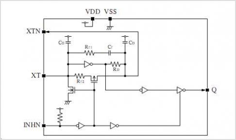
The oscillator tube is a high-voltage vacuum tube sometimes known as a pliotron. In Fig. 28-2 the grid voltage is supplied by a feed-back coil inductively coupled to the variable inductance L. The condenser CR replaces the condensers Cz and C3 of Fig. 28-1. 🔗 External reference
Related Circuits
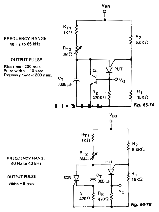
The variable oscillator circuit incorporates active components to discharge the timing capacitor CT, as illustrated in Fig. 66-7A. An alternative method is presented in Fig. 66-7B. The variable oscillator circuit is designed to generate oscillating signals with adjustable frequency characteristics....
The CYWUSB6953 is a comprehensive Radio System-on-Chip (SoC) device that facilitates the implementation of various simple RF systems using a single chip and a few discrete components. It is specifically designed for low-cost wireless systems that operate within the...
Hartley oscillators are inductively coupled, variable frequency oscillators that can be series or shunt fed. They feature a center-tapped inductor and a tuning capacitor, which simplifies the circuit construction. The schematic includes a buffer stage and an amplifier stage...
Unlike conventional small-signal methods, employing large-signal, time-domain design techniques facilitates the development of low-noise grounded-base oscillators suitable for VHF/UHF applications. The implementation of large-signal, time-domain design techniques in the creation of grounded-base oscillators represents a significant advancement in the field...
This is a resistance-tuned oscillator that operates in three frequency ranges from 35 cycles per second (cps) to 35,000 cps. A significant challenge with resistor/capacitor tuned bridges is maintaining a constant output level across a full decade frequency range....
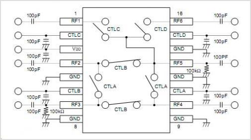
The CAMD CM8870 CM8870C offers complete DTMF receiver functionality by combining both the band-split filter and digital decoder capabilities into a single 18-pin DIP, SOIC, or 20-pin PLCC package. The CM8870C is produced using advanced CMOS process technology, ensuring...