
Audio Oscillators
The resistance-tuned oscillator employs a Wien bridge configuration, which is known for its stability and precision in generating sine wave signals. The oscillator's design utilizes a combination of resistors and capacitors to achieve the desired frequency output. The non-linear feedback mechanism, implemented through the 3-watt light bulb, introduces a unique approach to maintaining amplitude stability. As the oscillation amplitude varies, the light bulb's resistance changes, effectively adjusting the feedback loop to ensure that the oscillator remains within its optimal operating range.
The two models, 200A and 200B, demonstrate versatility in application, allowing users to select the appropriate frequency range for their specific needs. The inclusion of a two-stage power amplifier enhances the output capability, making it suitable for driving various loads while maintaining low distortion levels. The front panel controls provide user-friendly access to adjust output levels, with the calibration of dials ensuring accurate frequency readings.
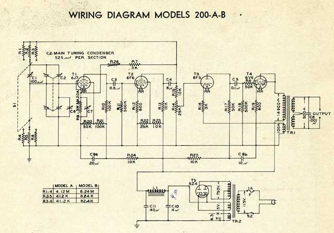
The historical significance of these models reflects the innovative spirit of early HP engineering, as evidenced by the meticulous craftsmanship and attention to detail in their construction. The documentation provided in the original instruction manual serves as a valuable resource for understanding the operational principles and specifications of these early electronic instruments. The integration of measurement tools within the 205AG model signifies a forward-thinking approach to testing methodologies, addressing the challenges of measurement accuracy in an evolving technological landscape.It is a resistance tuned oscillator covering from 35 cps (frequency unit was the cycle at this time) to 35, 000 cps in 3 ranges. The major problem with such a resistor / capacitor tuned Bridge is to obtain a constant level output over a full decade frequency range.
Bill Hewlett solved the problem by inserting a non-linear element in the feedback loop of the oscillator. This element controls the amount of feedback in accordance with the amplitude of oscillation and consequently maintains the proper operating point in the system. And what makes the idea a genius one is that the non-linear element is nothing else than a simple 3 Watts light bulb.
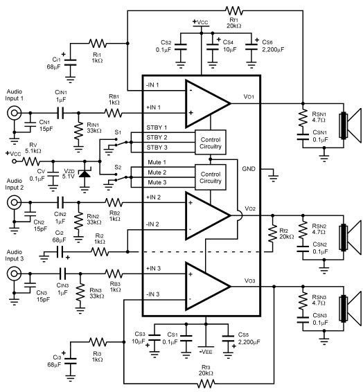
As shown in the wiring diagram below, two options with different frequency ranges were available: the 200A and 200B. A small modification of 6 resistors values resulted in different frequency ranges 35 to 35, 000 cps for the 200A and 20 to 20, 000 cps for the 200B.
All other specifications are common for the two units. A two-stage power amplifier with transformer-coupled output delivers 1 Watt into a 500 ohm resistance load. The output voltage is controlled ahead of the output amplifier from a front panel level control. The total harmonic distortion is lower than 0. 5 %. The HP 200B with rounded corners shown in this photo was hand built, probably in the second garage ( 481 Page Mill Road ) in 1940, and may have been handled by Bill and Dave themselves.
It is so old, they do not even have a HP company logo yet. Units with this particular case style are very rare today. Click on picture or link below for a PDF (2. 5 Mb) of the original instruction manual published in 1943. The manual include schematics, parts list, and chassis layout of the four different models produced by HP in 1943. The HP 200B with rounded corners shown in this photo comes from the Kenneth Kuhn collection. This unit was manufactured in 1941, just after the introduction of the first HP logo, probably at the Polly and Jake`s location and may also have been handled by Bill and Dave themselves.
Professor Kenneth Kuhn of the University of Alabama Birmingham is the owner and curator of one of the world`s largest collections of HP original early instruments. Almost every instrument produced by Hewlett Packard during the first 20 years can be seen on his Web Site.
Ken`s site is also a huge source of information on the HP history. The dial of all these instruments is calibrated directly in cycles for the lowest range. A switch selects the range and indicates the power multiplying factor. The dial calibration of Models 200A, 200B and 200C covers approximately 180 degrees, with an equivalent scale length of about 60 inches. "Main tuning dial of the 200i, which is an oscillator of the band-spead type, intended for comparison work.
The dial is calibrated over approximately 300 ° with effective scale length about 90" and range of 6 cps to 6 Kc. Each Model 200i is carefully hand calibrated to insure maximum accuracy. " The 205AG brought the output level to 5 Watts into an external load of 50, 200, 500 or 5000 ohms with a distortion of less than 1 % from 20 cps to 20, 000 cps.
As shown in the block diagram below the signal source is the model 200B basic circuitry followed by a 5 Watt (2 x 6L6 tubes), push-pull amplifier whose output is applied to the network under test through a 110 dB, 1 dB step attenuator and a line matching transformer. The control part of the 205AG integrates two vacuum tube voltmeters, one to measure the input and the second to measure the output of the device under test.
This is the first example of an HP product that provides answers to multiple problems found in production testing. Combining different tools in a single unit results in many advantages for instruments of this era where temperature drift and component aging were significant sources of measurement uncertainty.
The lowest-frequency HP oscillator using the RC, Wien-bridge tuning circui 🔗 External reference
Related Circuits
The objective of this project was to design a compact portable mixer powered by a 9V PP3 battery, while ensuring high-quality performance. The mixer consists of three primary modules, which can be customized in quantity and arrangement to meet...
This amplifier features high fidelity (Hi-Fi), high sensitivity, low power consumption, and low distortion, making it an excellent choice for high fidelity sound systems. The process of creating a printed circuit board (PCB) can be accomplished in a few...
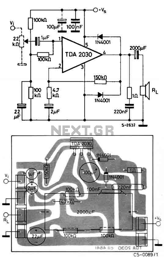
The circuit utilizes the TDA2030, a monolithic integrated circuit housed in a Pentawatt package, designed for use as a low-frequency class AB amplifier. It typically delivers 14W of output power (with a distortion factor of 0.5%) at 14V with...
The LM4782 utilizes a protection system known as National Self Peak Instantaneous Temperature (Ke) (SPiKeTM). SPiKe safeguards the output of the LM4782 against over-voltage on the load, short circuits to ground, and provides temperature protection by monitoring instantaneous temperature....
Designed for communications use, this equalizer circuit utilizes a Mitsubishi M5226P audio equalizer IC to modify frequency response. It operates with a supply voltage ranging from 9 to 20 V. Capacitors C6 through C16 are polyester film capacitors with...
This circuit is not easy to build, but it provides excellent audio quality. It serves as a high-quality preamplifier, capable of driving high-quality power amplifiers while delivering good sound. The described circuit functions as a high-fidelity audio preamplifier, designed to...
Warning: include(partials/cookie-banner.php): Failed to open stream: Permission denied in /var/www/html/nextgr/view-circuit.php on line 713
Warning: include(): Failed opening 'partials/cookie-banner.php' for inclusion (include_path='.:/usr/share/php') in /var/www/html/nextgr/view-circuit.php on line 713