
High Impedance Amplified Telephone Line Tap

The amplified telephone line tap circuit is engineered for discreet audio monitoring of telephone line signals. The high input impedance ensures that the tap does not load the phone line, preserving the integrity of the call. The electrical isolation is critical to prevent interference with the main circuit, ensuring that the tap operates independently without affecting the phone's functionality.
The LM386 audio amplifier is a low-voltage audio power amplifier that is widely used in various audio applications. In this circuit, it is configured for a voltage gain of 200, which provides significant amplification of the audio signal captured from the phone line. The output stage of the LM386 is capable of driving an 8-ohm speaker, making it suitable for direct audio playback or further processing.
The transformer sourced from an analog modem serves a dual purpose: it provides the necessary impedance matching between the phone line and the amplifier while also ensuring electrical isolation. This isolation is essential for preventing any potential feedback or noise that could arise from the circuit interacting with the phone line.
For optimal performance, especially in environments with potential electrical noise, grounding considerations are vital. Connecting the circuit ground to the building's electrical ground can help mitigate any noise that may be introduced by external electrical sources. However, this grounding is unnecessary when the circuit is powered by batteries, as they provide a clean power source devoid of such noise issues. It is important to analyze the specific application requirements to determine the best grounding strategy, particularly when using DC power supplies, which may introduce unwanted noise into the system.This is an amplified telephone line tap, which is designed to be minimally invasive. The interconnect to the phone line has a large input impedance, and is electrically isolated from the main electronics of the circuit. I designed this for use with a DTMF controlled relay driver, which did not come with an interface for direct connection to the ph
one line. When properly set up, the output audio from the tap is very clear, and the tap causes no disturbance to the phone line, and is essentially undetectable. The LM386 audio amplifier is set up for a voltage gain of 200, and the output is capable of driving an 8 ohm speaker.
The transformer used is from an analog modem. Depending on the application, it may be necessary to connect the circuit ground to the electrical ground of the building to reduce noise pickup (this is not necessary with batteries, but some DC power supplies will cause problems). 🔗 External reference
Related Circuits
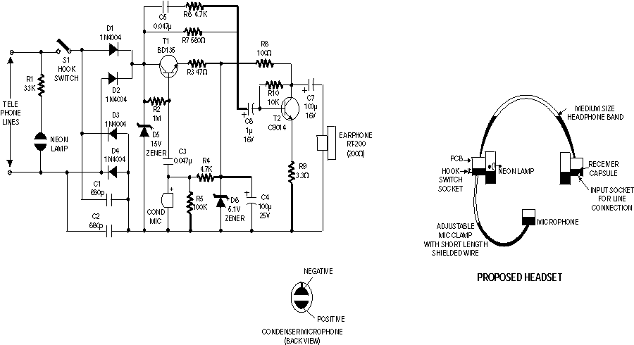
Telephone headgear. A compact, inexpensive, and low component count telecom headset can be constructed using two readily available transistors and a few other electronic components. The design of a compact and cost-effective telephone headset can be achieved using a minimal...

The automatic alarm circuit comprises a DTMF automatic dialing system, a password control circuit, a voice detection and alarm circuit, a telephone interface circuit, a power supply circuit, and a keyboard display circuit. The automatic dial-up alarm utilizes the...
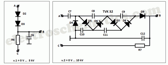
This high voltage converter circuit begins with a 30-volt power supply and is capable of delivering output voltages ranging from 0 to 3 kV for version 1, or from 0 to 10 kV for version 2. The high voltage converter...
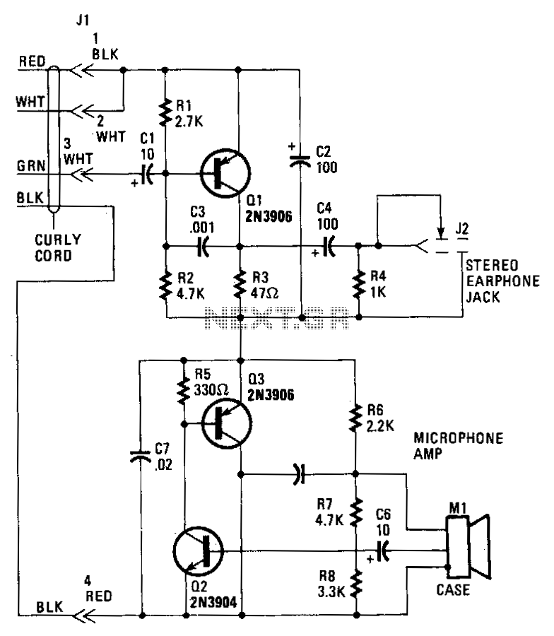
Transistor Q1 in the headset amplifier circuit amplifies the 30 mV signal intended for the earphones to 0.5 V, which is sufficient to drive stereo earphones. Capacitor C1 blocks any DC current from shorting back into the telephone base....
The circuit is a microphone amplifier designed for low impedance microphones, approximately 200 ohms. It operates with stabilized voltages ranging from 6 to 30 VDC. If the impedance adapter section with T1 is not constructed, the circuit can be...
Once again my collection of projects creation has been interrupted by another necessity. Patrick and other people have asked me for a circuit of a VHF power amplifier. These circuits are my "standard" building blocks that can be used...