
2 Watt VHF linear amplifier
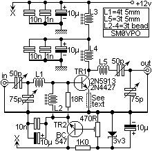
The VHF power amplifier circuit described operates effectively in the frequency range of 50MHz to 170MHz, with specific tuning capabilities for 100MHz. The design allows for flexibility in component scaling to accommodate various frequency bands, ensuring adaptability for different applications. The circuit is capable of delivering a gain of approximately 14dB at an output power of 2 Watts, with a decrease in gain at higher output levels, reaching 12dB at 20 Watts.
Key components include RF chokes, which are critical for maintaining stability and performance. L3, constructed with 20 turns of 22SWG wire on a ferrite ring, serves as a significant choke capable of handling the necessary current. L4 is designed with three or four turns of wire around binocular ferrite beads, optimized for higher power applications. Care must be taken not to scale the inductors for different frequencies, as this could adversely affect performance.
Tuning the amplifier involves adjusting the input and output capacitors for maximum supply current and output power, respectively. This iterative tuning process is essential for optimizing performance and achieving the desired gain. The circuit can be cascaded for higher output, allowing for configurations that provide up to 100 Watts using parallel PA transistors, enhancing versatility for various RF applications.
The biasing circuit, which includes TR2, regulates the voltage to the amplifier, ensuring proper operation of the transistors. Selection of the appropriate transistor is crucial; smaller transistors like the BC547 are suitable for lower power applications, while larger devices such as the 2N3053 are recommended for higher power levels. The bias current settings are critical for ensuring optimal performance without compromising signal integrity.
Safety considerations are paramount, particularly regarding RF exposure and power supply currents. The circuit requires a low pass filter to mitigate harmonic emissions and protect the connected antenna. Additionally, precautions must be taken to prevent excessive current draw and potential damage to components, especially in high-power configurations. The use of appropriate resistors in the emitter circuit can help manage power output and gain, providing further control over the amplifier's performance.
Overall, this VHF power amplifier circuit provides a robust solution for RF amplification needs, with careful attention to component selection, tuning, and safety protocols ensuring reliable operation across its specified frequency range.Once again my collection of projects creation has been interrupted by another necessity. Patrick and other people have asked me for a circuit of a VHF power amplifier. These circuits are my "standard" building blocks that can be used to amplify RF power signals, from 50MHz to 170MHz, just a few component changes are required. The circuit diagrams shown are "normalised" for 100MHz and will tune about 80MHz through to 120MHz. Simply scale the components up or down if you want to go down or up in frequency bands. The circuits as shown will give a gain of about 14dB with an output power of about 2 Watts (input = 100mW).
With an output power of 20 watts the gain falls off to just 12dB at 100MHz or just 10dB at 170MHz. L3 is a huge RF choke, made using typically 20 turns of 22SWG wire in a ferrite ring. The wire must be thick enough to carry the PA current. For low powers a small ferrite is more than sufficient. Do NOT scale this inductor for other frequencies. L4 is made using typically three or four turns of 22SWG enamelled wire inside a two ferrite beads side-by-side, as a pair of biniculars. For higher powers you should ideally use a larger two-hole binocular ferrite core. Tuning up the PA is quite easy, tune the two input caps for maximum supply current. Then tune the two output caps for maximum output power. The two caps are inter-related so you will just have to tune alternately until no further changes are required.
Repeat the tuning again but for maximum output power on both occasions. You should be able to achieve 14dB of gain for 2 watts output power, but a lot depends upon the device you are using. You can use two of these circuits cascaded to give a 20-watt output FM amplifier with only 100mW of drive.
The amplifier as shown was first built as a 2-watt amplifier but then extended to give 100 watts using two parallel PA transistors. The drive level was 2.5 watts. 100 watts is not exactly QRP but when you are running your 25mW QRP transmitter it can sometimes be very satisfying to have the power - QRPers are very often stamped on and it can be nice to do a bit of stamping on certain occasions.
Please be aware that even with just 12v (13.8v nominal) and outputs of 20 watts or so, you can still get a nasty RF burn. I have lit cigarettes using the 100 watts version. Also be aware of the supply current. For 100 watts, the supply current was a little over 20 Amperes for the linear version!! You must also use a Low Pass filter between the amplifiers and the antenna, just as you should with any other amplifier.
L2 is typically four turns of "thin" wire on a single ferrite bead for all frequency bands. L1 and L5 are both close-wound 22SWG enamelled wire on an air-cored 5mm Dia. former. L1 and L5 should physically be mounted as far away from each other as possible and in a different plane (if one is vertical the other should be horisontal). The 50pf and 75pf preset caps can be any old caps for low power work, but above about one watt you should select high-power rated components.
Here we have added TR2 to provide the 0.7vDC bias in the form of a simple series regulator. For driving small transistors like the 2N3866 and 2N4427, TR2 can be a simple BC547 or a 2N2222. For driving higher power amplifiers you should use a larger transistor fitted with a heatsink. A 2N3053 or BCY51 device should be fine. Before switching on the main DC power to the amplifier, set the bias potentiometer to minumum voltage, apply the power and adjust the pot until TR1 draws a little current. For 500mW to 5 watt devices you should set TR1 current to about 5mA to 50mA. With 5 watt to 25 watt amplifiers you should set the TR1 current to about 50mA to 200mA. Don't be to mean with the standing DC current as it is this that is keeping the FCC of your back by giving you a clean transmission (assuming you have a licence).
Now you can align the complete Linear PA. The optional resistor in the emitter will restrict the maximum output power by reducing the gain of the whole amplifier. This resistor should be typically 12 ohms for low power devices, such as the 2N3866 or 2N4427 devices.
For BLW90 or other high-power devices the emitter resistor should be a total short-circuit. In this event the supply should also be protected with a fuse. In high-power circuits do NOT use relay switching or you will burn out relays. The circuit should not draw any significant current with no signal. The 18 ohm resistor should also be reduced for power devices, typically 5R6 for a 20-watt amplifier. 🔗 External reference
Related Circuits
This circuit is primarily designed to offer a microphone input for standard home stereo amplifiers. Utilizing a battery supply effectively eliminates the risk of low-frequency hum interference from the mains, and simplifies the connection to the amplifier by removing...
This circuit design is a Class A amplifier that utilizes both AC and DC feedback. The bias is stabilized at 15 mA of the collector current through the use of DC feedback from the collector. The AC feedback, which...

This is a circuit for an accelerometer amplifier. It is a straightforward circuit. A precision accelerometer requires an inverting mode amplifier since these devices typically output charge. This amplifier converts charges into a voltage output. The circuit presented below...
A 12dB/oct Butterworth filter circuit is designed to achieve a flat frequency response. The optimal value for the circuit's Q factor is 0.707, which ensures a flat characteristic. The feedback capacitance must be selected to maintain high capacity and...
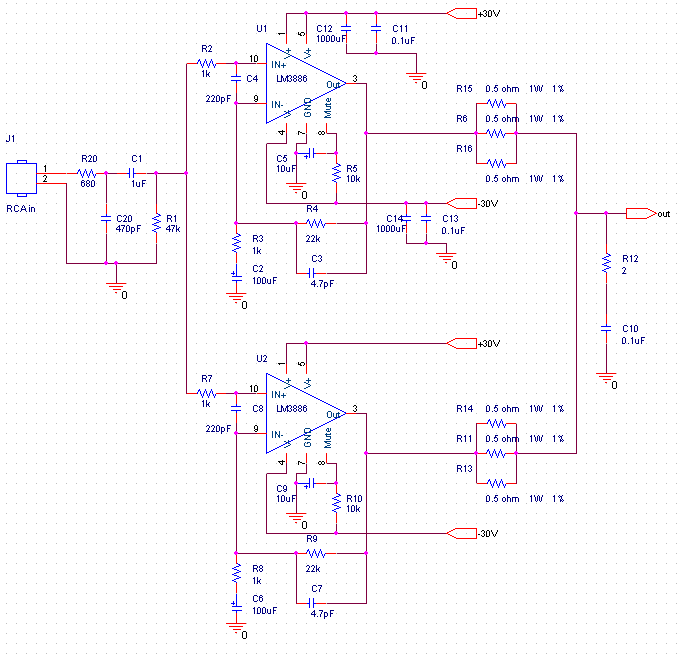
This audio amplifier design utilizes two LM3886 chips per channel in a parallel configuration, based on the PA100 parallel amplifier detailed in National Semiconductor's application note AN1192. The amplifier can deliver approximately 50W into an 8-ohm speaker and 100W...
The CXA1619BM and CXA1619BS are one-chip FM/AM radio integrated circuits developed by Sony Corporation. These ICs are intended for use in radio-cassette tape recorders and headphone tape recorders, offering a variety of functions. The CXA1619BM and CXA1619BS are designed to...
Warning: include(partials/cookie-banner.php): Failed to open stream: Permission denied in /var/www/html/nextgr/view-circuit.php on line 713
Warning: include(): Failed opening 'partials/cookie-banner.php' for inclusion (include_path='.:/usr/share/php') in /var/www/html/nextgr/view-circuit.php on line 713