
High-Pass 20HZ to 200HZ Filter

The described circuit is a high-pass filter designed to allow frequencies above a certain cutoff frequency to pass while attenuating frequencies below that threshold. This particular filter is adjustable, with a variable frequency range from 20 Hz to 200 Hz, making it suitable for various audio applications where the elimination of low-frequency noise or interference is desired.
The core components of the circuit include a double potentiometer rated at 47 kΩ, which serves as the primary means of adjusting the cutoff frequency. The potentiometer is connected in such a way that it varies the resistance in the filter circuit, thus altering the frequency response. As the resistance is increased, the cutoff frequency shifts upward, allowing higher frequencies to pass while blocking lower frequencies.
The circuit topology typically involves a capacitor and resistor in series, with the output taken across the capacitor. The interaction between the capacitor and the variable resistor determines the filter's cutoff frequency. The relationship can be expressed by the formula:
\[ f_c = \frac{1}{2\pi RC} \]
where \( f_c \) is the cutoff frequency, \( R \) is the resistance (in ohms), and \( C \) is the capacitance (in farads). By selecting appropriate capacitor values and adjusting the potentiometer, the user can effectively set the filter to operate within the desired frequency range.
In practical applications, such a high-pass filter can be used in audio processing to enhance sound clarity by removing unwanted low-frequency sounds that may muddy the overall audio signal. This is particularly useful in environments where various sound sources are present, allowing for a cleaner and more defined output.
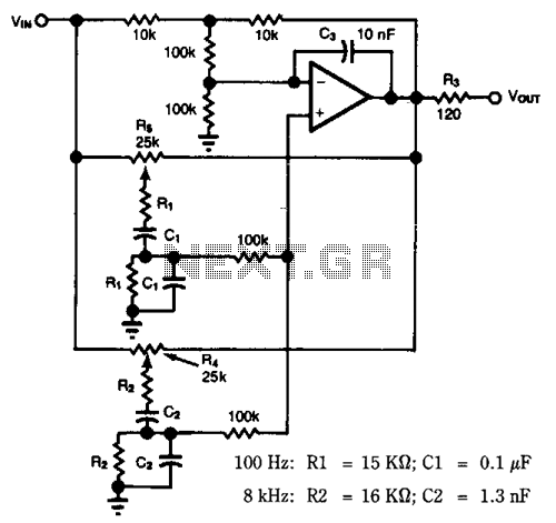
The schematic representation of this circuit would typically include the double potentiometer, a capacitor, and the necessary input and output connections, clearly indicating the points at which the frequency response can be monitored and adjusted. The design ensures that the filter can be effectively integrated into larger audio systems or used standalone for specific sound signal processing tasks.A simple circuit, High-Pass filter, variable between frequencies 20HZ until 200HZ, useful in a lot of cases elaboration of sound signals. The regulation is achieved with the double potesometer 47K? and the frequency response in his two extreme places, appears in the schematic. 🔗 External reference
Related Circuits
The core of a typical RMS calibrated AC voltmeter consists of a rectifier and averaging filter. To create a precision full-wave rectifier, the averaging function can be removed by eliminating capacitor C2, while deleting capacitor C1 will enable the...
Most audio tone controls affect midband gain and often create booming or hissing sounds when activated. These problems can be avoided by using a dual Wien-bridge filter to provide independent control of the treble and bass frequencies. Experiments with...
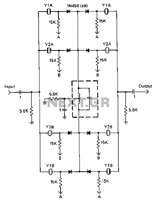
A 9-12V DC power supply is connected to control point A or point B for an amateur communication receiver IF amplifier, offering two distinct options. The power frequency is set at 455 kHz with a bandwidth of 500 Hz....
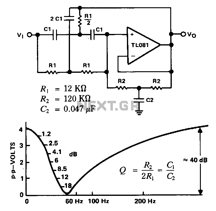
This filter is utilized to reject or block a specific frequency or range of frequencies. Such filters are commonly integrated into audio and instrumentation systems to eliminate a single frequency, for instance, 60 Hz. Commercial-grade components with a tolerance...
High-order filters are typically designed with two or more cascaded sections. An order 4 filter requires only one operational amplifier integrated circuit (OA IC), allowing for lower distortion. High-order filters are essential in various applications, including audio processing, signal conditioning,...
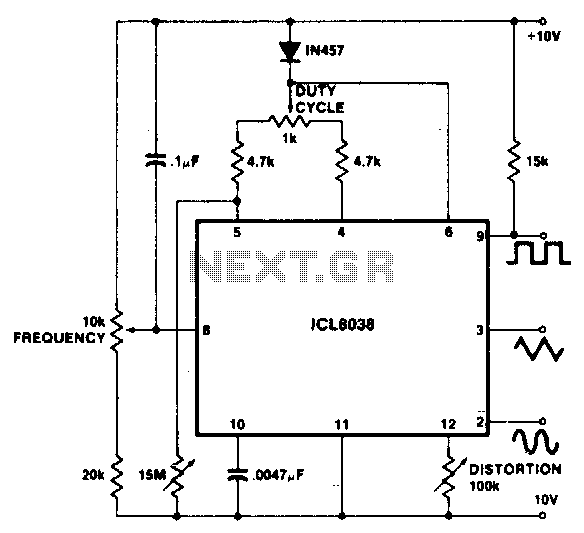
To achieve a 1000:1 sweep range, the voltage across the external resistors Ra and Rb must be reduced to nearly zero. This necessitates that the maximum voltage on control pin 8 surpasses the voltage at the top of Ra...