
High PoE made easy
The circuit diagram depicts one of two HPOE interfaces in a 47-watt dual Ethernet pair configuration. Each bridge rectifier consists of two n-channel and two p-channel MOSFETs, each biased on by a 150k resistor connected to the opposite polarity input line. The gates are safeguarded by low-current Zener diodes (with a test current of 50 microamps). Only the two MOSFETs that correspond to the correct polarity will activate. The drain-source diodes within the MOSFETs function as the bridge rectifier until the circuit can charge the MOSFET gates via the 150k resistors. The integrated HPOE interface simplifies the circuit by providing all necessary interface and hot-swap functionalities.
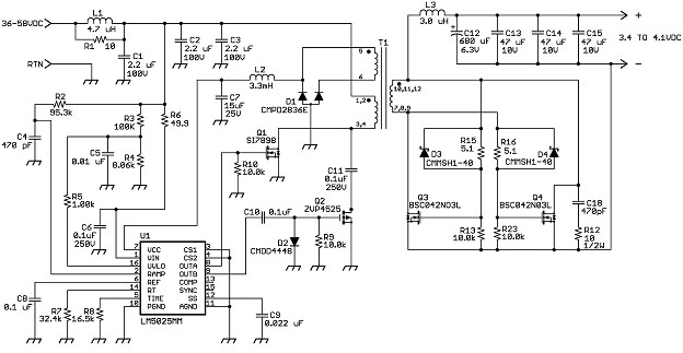
The circuit also includes a DC/DC converter, depicted in a separate figure. This active-clamp forward converter, utilizing the LM5025 controller, achieves very high efficiency and eliminates the need for isolated feedback. The LM5025 generates a ramp voltage across capacitor C4, which subsequently controls the duty cycle. The duty cycle becomes inversely proportional to the input voltage, resulting in a nearly constant output voltage. The availability of capacitors with 1 percent accuracy at a low cost allows for excellent regulation without feedback requirements. The circuit design avoids any components for current sensing, thereby eliminating associated losses. Basic current limiting circuitry is integrated into the hot-swap section preceding the forward converter, along with current limiting in the post-regulators at the output, which simplifies the design while ensuring adequate protection. The LM5025 controller requires only about 10 mA of current, necessitating a large inductance to prevent peak charging since the rectifiers are not synchronous. However, due to the low current requirement, the inductor can be physically small, with a DC resistance of approximately 32 ohms. While a linear regulator could be powered from the high input voltage to fulfill this function, it would incur significant power loss, and the cost would be comparable.The IEEE standards for so-called "high power-over-Ethernet" (HPOE) have yet to be resolved, but most designers expect a 53 VDC source, usable current from each line of about 750 mA, and a total cable resistance of 12. 5 ohms. If you design for what will probably be the worst-case scenario, expect 46 VDC (48 V nominal) at 720 mA and 12.
5 ohms. At 72 0 mA, the cable would produce a drop of 9 volts, leaving 37 VDC to work with. In this case, about 26. 6 watts would be available at the end of the cable. The typical power stage running from this input would yield a bit over 20 watts. Unfortunately, that`s not nearly enough power for some applications. One solution is to use multiple Ethernet lines, but that topology raises the problem of power sharing. Here`s how to deal with that issue. Conventional HPOE interfaces consist of a polarity-protecting bridge rectifier and a hot-swap section with a power-over-Ethernet interface, followed by an isolated converter with regulated outputs.
Preferably, these outputs won`t be load-dependent and will have good transient response. Typical designs use isolated feedback to produce one voltage, typically 5 VDC, which is then converted to various other voltages for the given application. In some cases multiple outputs are attempted from one feedback loop, but the regulation is very dependent on load.
In either case, the losses in the bridge rectifiers and converters leave you with rather poor efficiency. Also, isolated feedback tends to provide rather poor transient response. The point of HPOE, on the other hand, is to get as much usable power from as few Ethernet lines as possible without sacrificing performance.
That`s possible in the example below, which addresses both the HPOE interfaces and the power converters to to provide an additional efficiency boost of several percent and excellent transient response. Figure 1 shows one of the two HPOE interfaces in a 47-watt dual Ethernet pair design. Two n-channel and two p-channel MOSFETs form each bridge rectifier. Each is biased on by a 150k resistor from the opposite polarity input line. The gates are protected by low-current zener diodes (test current is 50 microamps). Only the two MOSFETs with the correct polarity will be turned on. The drain-source diodes in the MOSFETs act as the bridge rectifier until the circuit is able to charge the MOSFET gates through the 150k resistors.
The integrated HPOE interface lends some simplicity to the circuit, providing all necessary interface and hot-swap functions. Figure 2 shows one of the two DC/DC converters. The active-clamp, forward converter, using the LM5025 controller, delivers very high efficiency and does away with the need for isolated feedback.
The LM5025 generates a ramp across capacitor C4, which in turn controls the duty factor. The duty factor becomes inversely proportional to input voltage and produces a nearly constant output voltage. Fortunately, capacitors with 1 percent accuracy cost only a few pennies these days, and as applied in this circuit provide excellent regulation without the need for feedback.
No components are needed for current sensing and thus any losses associated with them are eliminated. The basic current limiting circuitry in the hot-swap section ahead of the forward converter and the current-limiting in the post regulators at the output simplify the design while providing adequate protection.
The current required by the LM5025 controller is only about 10 mA, so a large value of inductance is necessary to prevent peak charging since the rectifiers are not synchronous. But because the current is very low, the inductor is physically very small. Its DC resistance is about 32 ohms. A linear regulator could be powered from the high input voltage to provide this function, but the power loss would be significant while the cost would be about the same.
🔗 External reference
Related Circuits
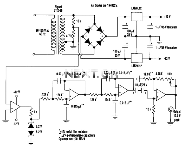
A highly stable 60-Hz sine wave can be delivered with this circuit, which offers a different and much simpler approach to achieving a stable amplitude. Capacitor coupling in the last stage removes any DC component caused by unequal Zener...
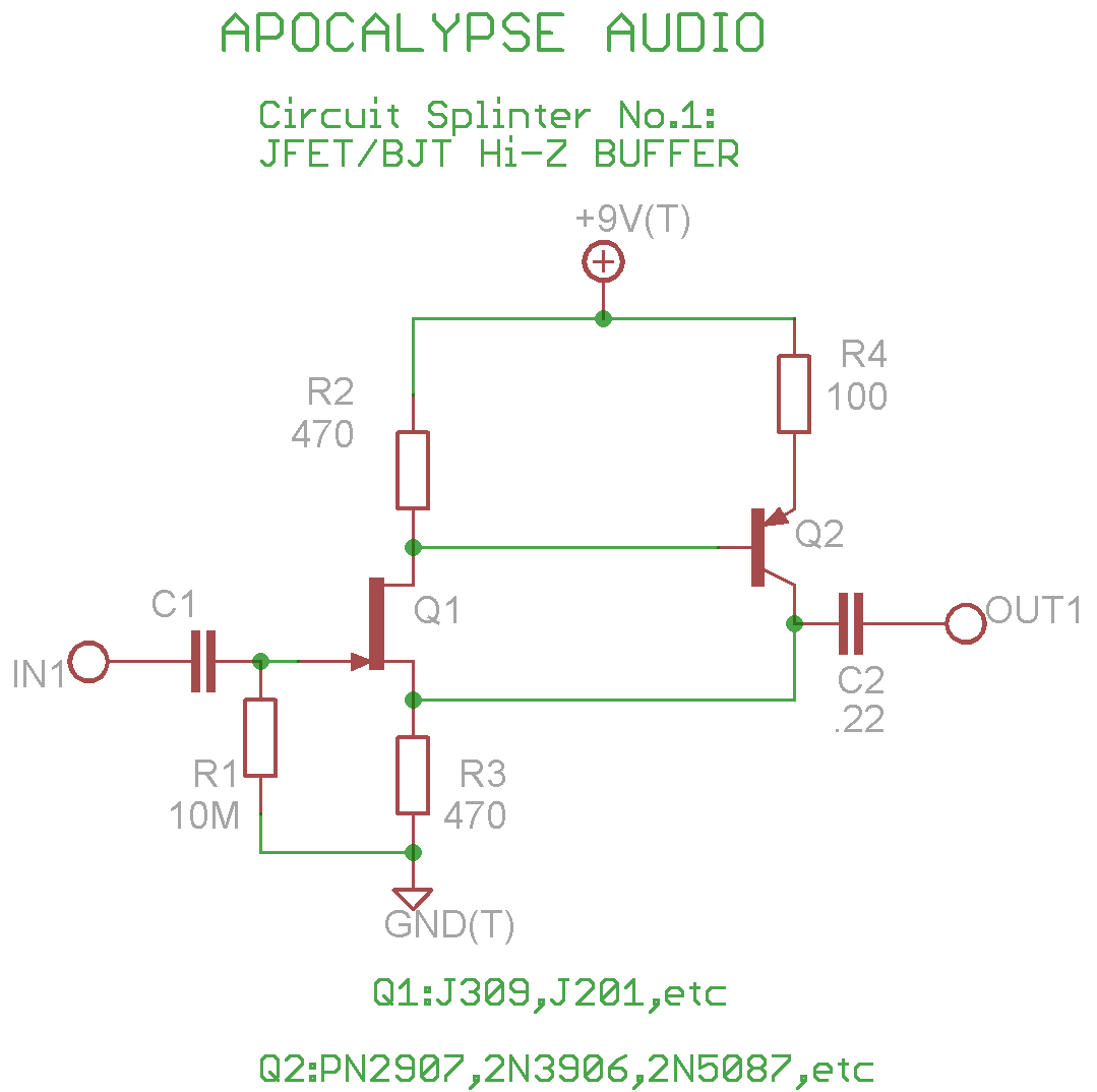
This is a common circuit often found in various resources, yet it appears to be less prevalent in stompbox applications. The circuit utilizes an NPN JFET DC coupled with a PNP BJT. The FET provides a significantly higher input...
This cost-effective circuit can be connected to an air conditioner, refrigerator, or any other advanced electrical appliance for protection. This circuit serves as a protective device for sensitive electrical appliances such as air conditioners and refrigerators. It is designed to...
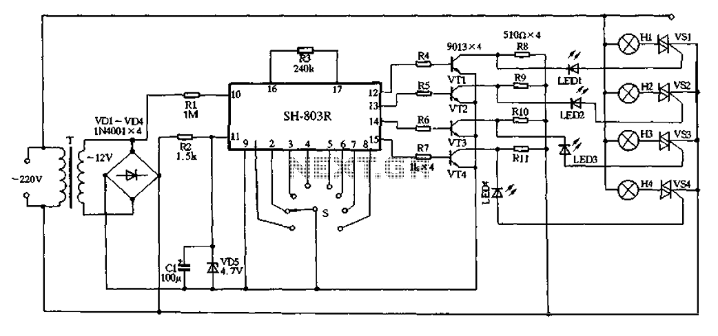
22V AC is supplied through thyristors VSl to VS4 for lighting control. The current is routed through transformer T, followed by rectification using diodes VD1 to VD4, and regulated by VD5 to provide a filtered output of approximately 4.7V...
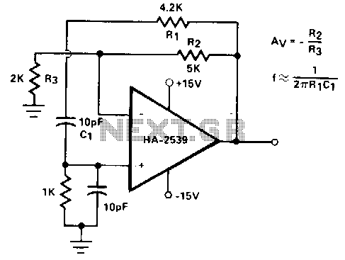
Intended primarily as a building block for a QRI transmitter, this 20-MHz oscillator delivers a clean 6-V peak-to-peak signal into a 100-ohm load. The 20-MHz oscillator functions as a critical component in the design of a QRI transmitter, providing a...
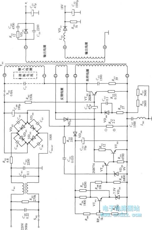
A high voltage switching stabilized voltage supply circuit is illustrated in the diagram. This is the switching power supply for an 80P type color television. It utilizes auto-excitation and a PWM circuit. The output is isolated from the power...