
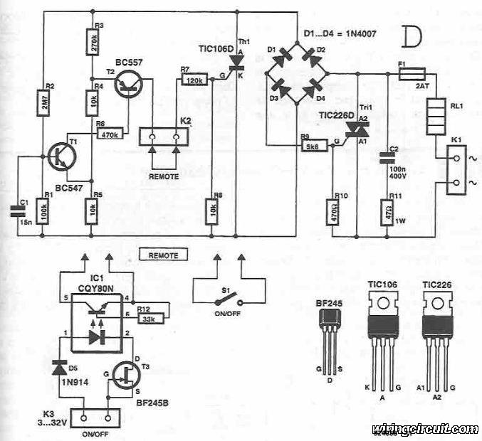
High Low Voltage Cutout Without Timer
This circuit serves as a protective device for sensitive electrical appliances such as air conditioners and refrigerators. It is designed to prevent damage caused by voltage fluctuations, overloads, and short circuits. The circuit typically incorporates essential components such as fuses, relays, and voltage regulators to ensure reliable operation.
The primary function of the circuit is to monitor the electrical parameters of the appliance. When the circuit detects an abnormal condition, such as an overcurrent or a voltage spike, it will automatically disconnect the appliance from the power supply to prevent potential damage. The use of a fuse provides an additional layer of safety, as it will blow if the current exceeds a specified limit, thereby interrupting the circuit.
Incorporating a relay allows for the automation of the disconnection process. When a fault condition is detected, the relay is activated, opening the circuit and cutting off power to the appliance. This mechanism can be reset either manually or automatically, depending on the design.
To enhance the circuit's functionality, a voltage regulator can be included to maintain a stable output voltage, protecting the appliance from voltage fluctuations that could lead to malfunction or damage. Additionally, the circuit may feature LED indicators to provide visual feedback on the operational status, allowing users to quickly ascertain whether the appliance is functioning correctly or if a fault has occurred.
Overall, this protective circuit is a crucial component for ensuring the longevity and reliability of electrical appliances, especially in environments where power quality may be inconsistent. Its simplicity and cost-effectiveness make it an ideal solution for both residential and commercial applications.This inexpensive circuit can be connected to an air-conditioner/fridge or to any other sophisticated electrical appliance for its protection. Generally, c.. 🔗 External reference
Related Circuits
This circuit diagram illustrates the design of a straightforward AC voltage converter that transforms 240V AC power into 110V AC. The circuit can effectively be utilized to power electrical devices that necessitate a supply voltage of 110V. The AC voltage...
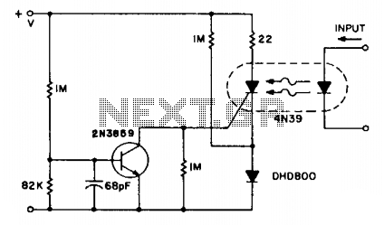
The SCR coupler circuit offers increased sensitivity to input signals as demonstrated. This enables the utilization of the more economical 4N39 (H11C3) with the drive currents exceeding 7 mA provided by the input circuit. The SCR coupler circuit is designed...
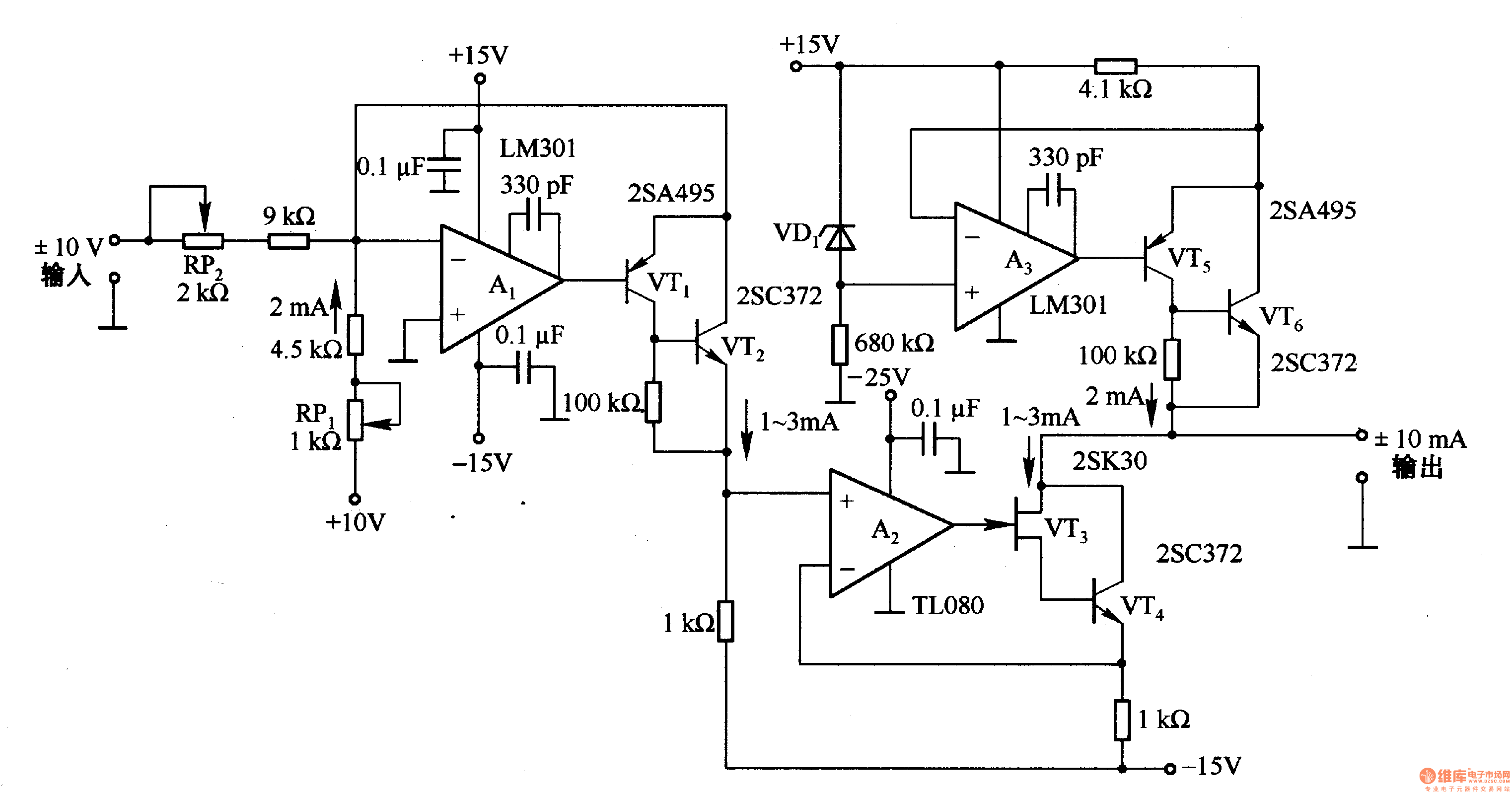
This circuit is designed for voltage-to-current conversion, specifically transforming a ±10V input voltage into a ±1mA output current. The conversion process is facilitated by operational amplifier A1 and transistors VT1 and VT2, which are responsible for altering the current...
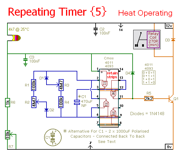
This timer circuit operates only when the temperature exceeds a predetermined level. An alternative version, known as Repeating Timer No. 6, functions while the temperature is below this preset level. The resistor R7 is used to set the temperature...
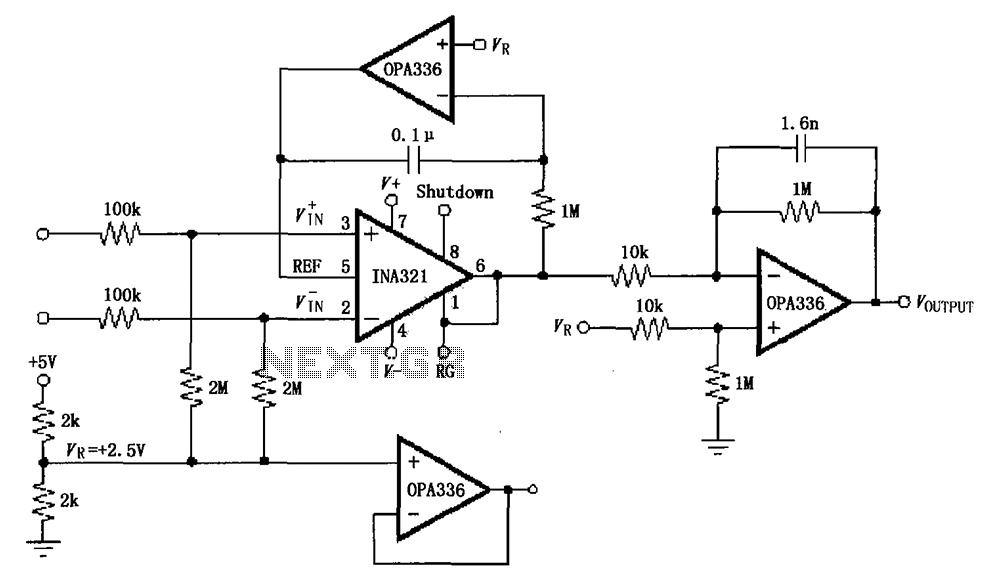
The INA321/322 forms a low-cost, medium-accuracy ECG amplifier circuit. The INA321 receives input signals from the patient's arm, amplifying them before sending the modified output to the operational amplifier OPA336. The OPA336 generates an output voltage from the inverting...

This circuit is designed as a countdown timer utilizing a countdown calculation. It employs the 555 integrated circuit (IC) as the primary control element. The 555 IC functions as a counter and a transistor switch to activate a relay...
Warning: include(partials/cookie-banner.php): Failed to open stream: Permission denied in /var/www/html/nextgr/view-circuit.php on line 713
Warning: include(): Failed opening 'partials/cookie-banner.php' for inclusion (include_path='.:/usr/share/php') in /var/www/html/nextgr/view-circuit.php on line 713