
High-speed laser diode driver
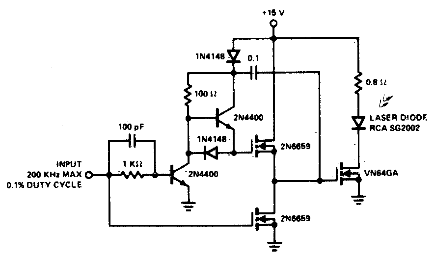
The described circuit employs a VMOS (Vertical Metal Oxide Semiconductor) totem pole configuration, which is essential for driving high-power switches such as the VN64GA efficiently. The primary function of the faster driver is to provide a significant peak gate current, which enables rapid switching of the MOSFET. This is crucial in applications where swift on-off transitions are necessary to minimize power loss and improve overall efficiency.
In the totem pole arrangement, two VMOS transistors are configured in a complementary fashion. One transistor is responsible for pulling the gate voltage high (turning the switch on), while the other pulls it low (turning the switch off). This configuration not only allows for a quick response time but also ensures that the gate capacitance of the VN64GA is charged and discharged effectively, leading to reduced switching times.
The peak gate current supplied by the driver is a critical parameter, as it must be sufficiently high to overcome the gate charge of the VN64GA. The driver circuit typically includes a dedicated power supply to provide the necessary voltage and current levels. It may also incorporate additional components such as resistors and capacitors to fine-tune the switching characteristics and enhance stability.
Overall, the use of a VMOS totem pole stage in conjunction with a fast driver significantly enhances the performance of high-power switching applications, ensuring rapid and efficient operation of the VN64GA MOSFET. This design approach is particularly beneficial in power electronics where efficiency and speed are paramount.A faster driver can supply higher peak gate current to switch the VN64GA very quicklyThe circuit uses a VMOS totempole stage to drive the high power switch 🔗 External reference
Related Circuits
The BTS412B functions as two high-side power MOSFET switches, while the BU271L components rated for 50V serve as the low-side switches. Together, these elements can form a bi-directional H-bridge DC motor drive circuit, as depicted in Figure 11-1l. This...
The ISL97676 can be utilized as an LED driver capable of managing six channels of LED current for TFT displays. This driver supports the operation of up to 78 LEDs with a voltage range of 4.5V to 26V, or...
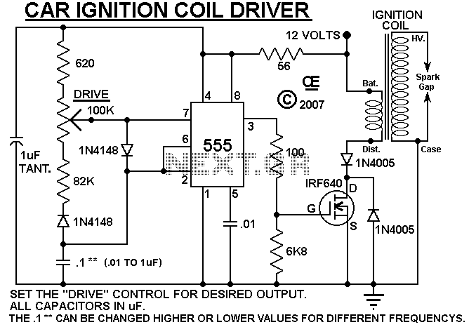
A simple design based on a 555 to drive a car ignition coil. This was designed for a small electric fence to protect a vegetable garden from small animals called marmots. Last year, they ate one of the crops...
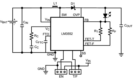
For this LED driver electronic project, a DC power supply circuit is required to provide an output voltage between 2.7V and 5.5V. The supply voltage must be applied between Vin and GND. The T/F jumper connects the T post...
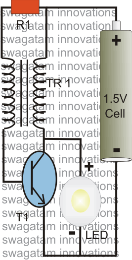
The post explains a simple 1 watt LED driver circuit using a single 1.5 V penlight cell through the joule thief concept. The coil may be wound over a T13 toroidal ferrite core using 0.2 mm or 0.3 mm...
A boost converter, such as the TPS61160/1, can be utilized with a 40V rated integrated switch FET to drive multiple LEDs in series. This configuration can help reduce output ripple. The TPS61160/1 is a highly efficient boost converter designed for...