
IN8510 and power motor driver circuit composed of DAC7520

The described circuit utilizes the BTS412B and BU271L components to create a robust and efficient H-bridge configuration suitable for driving DC motors in automatic door systems. The H-bridge topology allows for bidirectional control of the motor, enabling it to open and close the doors as required. The high-side switches, represented by the BTS412B, are responsible for connecting the motor to the positive supply voltage, while the low-side switches, represented by the BU271L, connect the motor to ground.
The integration of CMOS logic levels for controlling the four switches ensures compatibility with modern digital control systems, allowing for precise and efficient operation. The logical drive outputs from the BTS412B can be used to control additional components or provide feedback to a microcontroller, enhancing the system's functionality. The inclusion of an LED for fault indication is a critical feature, providing immediate visual feedback regarding the operational status of the circuit.
The 12kΩ resistance at the left leg midpoint when the switches are off acts as a safeguard against false open load detection by the BTS412B. This design consideration is essential for maintaining the reliability of the system, as it prevents unnecessary fault signals from being triggered during normal operation. The ability of the right BTS412B to detect actual open load conditions further enhances the circuit's fault tolerance, ensuring that any issues can be promptly identified and addressed.
Overall, this H-bridge motor drive circuit is well-suited for applications requiring reliable and efficient control of DC motors, particularly in automatic door mechanisms where safety and performance are paramount.BTS412B as two high-side power MOSFET switch and two BU271L 50v for the low-side switch, can be composed of bi-directional H-bridge DC motor drive circuit shown in Figure 11-1l. The circuit is an electrical automatic doors design, continuous current up to 6A. Four-leg switches are directly controlled by CMOS logic levels. Two BTS412B state output of the logical drive or a transistor, the LED displays the fault status. Left leg midpoint -to-ground resistance when 12ktl four H-bridge switches are turned off, will not be BTS412B mistaken Open load. Once open load occurs, the right of BTS412B can detect it and issue a fault signal.
Related Circuits
The two circuits below illustrate the application of the 555 timer to activate a relay for a specified duration by pressing a momentary normally open (N/O) push button. The circuit on the left can be used for longer time...
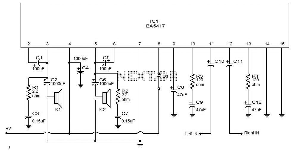
The BA5406 is a dual OTL (output transformerless) monolithic power integrated circuit (IC) featuring two high-output speaker amplifier circuits. It operates effectively with a supply voltage (Vcc) of 12 V and a load resistance (Rl) of 3 Ohms. At...
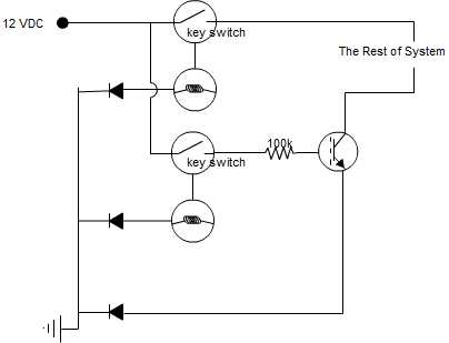
A circuit is being designed that incorporates two key switches, which must both be closed for current to flow through the circuit. The proposed circuit configuration employs two key switches connected in series. In this arrangement, the current can only...

This switching power supply circuit diagram is based on the MC33374 high-power voltage switching regulator IC manufactured by Motorola Semiconductor. The MC33374 switching power supply circuit will provide a maximum output power of around 90 W and requires few...
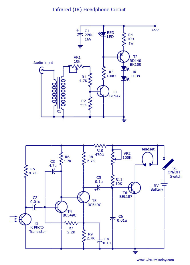
This document outlines a simple infrared (IR) headphone circuit designed for listening to television or radio without disturbing others. The IR headset is a preferable option for beginners compared to FM headsets due to its desirable sound quality that...

A neon lamp can easily be added to the phone line to act as a ring indicator. It is perfect for times when you cannot hear the phone. The integration of a neon lamp as a ring indicator in a...