
High Voltage Dc Generator Circuit
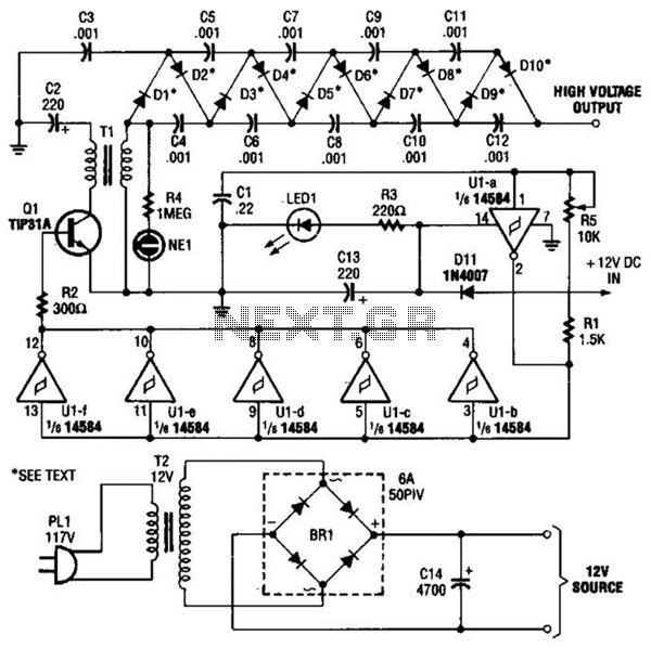
The miniature high-voltage DC generator circuit is designed for efficient voltage amplification and conversion. The core component, transformer T1, plays a pivotal role in stepping up the input voltage. The transformer is configured to ensure that the secondary winding generates the necessary pulsating DC signal. This signal is crucial for the subsequent voltage multiplier circuit, which is structured in a cascade arrangement of diodes and capacitors.
The voltage multiplier circuit, composed of diodes D1 to D10 and capacitors C3 to C12, operates on the principle of capacitive charge accumulation. Each stage of the multiplier contributes to the overall voltage output, with the capacitors storing energy during the charging phase and releasing it during the discharge phase. The careful selection of diode and capacitor specifications ensures that the circuit can handle high voltage levels without failure.
The oscillator circuit (U1-a) is integral to the operation of the generator, as it sets the frequency of the pulsating DC signal. The frequency is adjustable via potentiometer R5, allowing for fine-tuning to match the desired operational characteristics of the multiplier. The relationship between frequency and capacitive reactance is critical; a higher frequency minimizes reactance, optimizing the performance of the voltage multiplier.
Indicators such as LED1 and NE1 provide visual feedback on the operational status of the generator. LED1 indicates that power is being supplied to the circuit, while NE1 signals that high voltage is present at the secondary winding of T1. These indicators enhance the usability and safety of the circuit, ensuring that operators are aware of the system's status.
For testing and calibration purposes, connecting an oscilloscope with a high-voltage probe to the output of the voltage multiplier allows for precise measurement of the output voltage. This setup facilitates adjustments to R5, ensuring that the circuit operates at maximum efficiency and delivers the intended high-voltage output. Overall, this miniature high-voltage DC generator circuit exemplifies a well-engineered solution for generating high voltage from a low-voltage DC source. In the miniature high-voltage dc generator, the input to the circuit, taken from a 12-Vdc power supply, is magnified to provide a 10,000-Vdc output causing a pulsating signal, of opposite polarity, to be induced in Tl`s secondary winding. The pulsating dc output at the secondary winding of Tl (ranging from 800 to 1000 V) is applied to a 10-stage voltage-multiplier circuit, which consists of D1 through D10, and C3 through C12.
The multiplier circuit increased the voltage 10 times, producing an output of up to 10,000 Vdc. The multiplier accomplishes its task by charging the capacitors (C3 tlirough C12); the output is a series addition of the voltages on all the capacitors in the multiplier. In order for the circuit to operate efficiently, the frequency of the square wave, and therefore the signal applied to the multiplier, must be considered. The output frequency of the oscillator (Ul-a) is set by the combined values of Kv Rr>, and C{ (which with the values specified is approximately 15 kHz).
Potentiometer R5 is used to fine tune the output frequency of the oscillator. The higher the frequency of the oscillator, the lower the capacitivc reactance in the multiplier. Light-emitting diode LED1 serves as an input-power indicator, and neon lamp NE1 indicates an output at the secondary of Tl. A good way to get the maximum output at the multiplier is to connect an oscilloscope to the high-voltage output of the multiplier, via a high-voltage probe, and adjust potentiometer R5 for the maximum voltage output.
🔗 External reference
Related Circuits
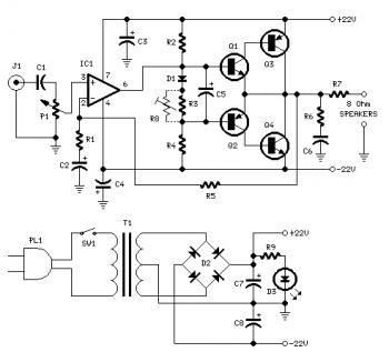
Proper grounding is essential for eliminating hum and ground loops. Connect the ground terminals of J1, P1, C2, C3, and C4 to the same point. Connect C6 to the output ground. An audio amplifier is an electronic device that...
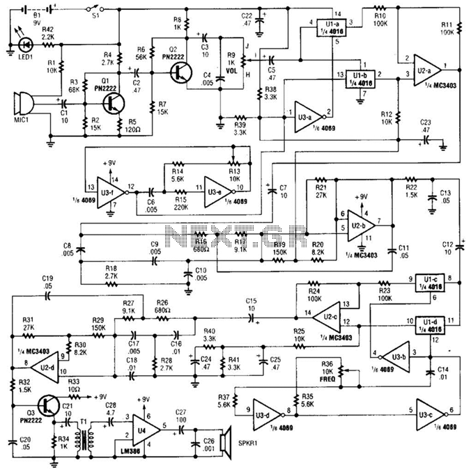
A complete schematic diagram of the voice disguiser is presented. Microphone MIC1 captures the voice signal and transmits it to an audio amplifier, which consists of Q1 and Q2, along with several supporting components. This amplifier features a low-pass...
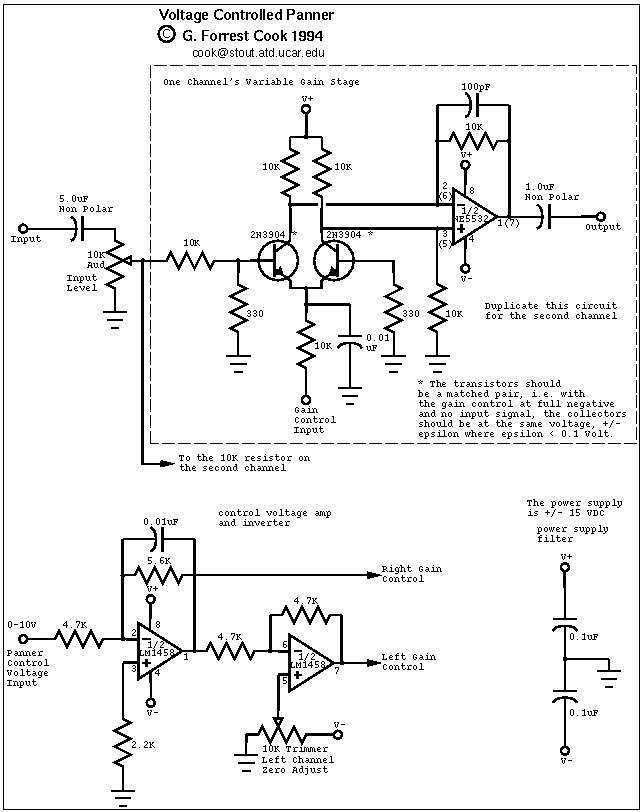
This circuit is used to convert a mono audio signal into a stereo signal that can be panned between the left and right channel by a 0-10V control signal, it is intended for analog synthesizer systems. The circuit is...
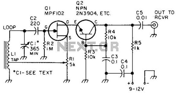
This preamplifier features a built-in regeneration control that enhances gain selectivity. CI represents a single or multi-gang AM broadcast-band tuning capacitor, while LI is a ferrite loop antenna tapped at approximately 15 to 25% of the total turns. This...
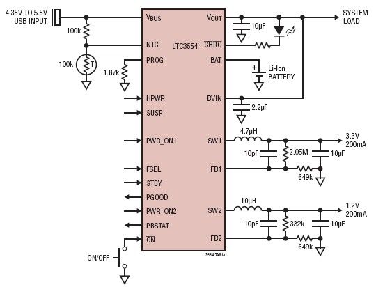
This micropower multifunction power management integrated circuit (PMIC) is designed using the LTC3554, manufactured by Linear Technology Corporation. It serves as a solution for portable Li-Ion Polymer battery-based applications. The LTC3554 integrates a USB-compatible linear PowerPath manager, a standalone...
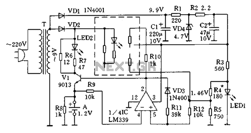
The circuit operates for 10 hours using constant current charging, providing convenience. The electricity from the secondary transformer T is stepped down, with the output directed through VD1 for rectification, followed by R1 and C1 for filtering. VD4 regulates...