
Four independent charging single battery automatic charger circuit

The circuit is designed to efficiently manage the charging of a rechargeable battery using a constant current approach. The primary components include a transformer, rectifiers, filters, comparators, and MOSFETs, which work in conjunction to maintain a stable charging voltage and current. The transformer steps down the AC voltage to a lower level suitable for the battery charging circuit. The rectification process converts the AC voltage to DC, which is then filtered to smooth out any ripples, providing a stable voltage output.
The use of LM339 comparators allows for precise monitoring of the battery voltage. The output of these comparators is critical for controlling the MOSFET, which acts as a switch in the charging circuit. The hysteresis introduced by VD3 and R11 is essential for preventing rapid on-off cycling of the charger, which could otherwise lead to inefficiencies and potential damage to the battery.
The charging indicators provide visual feedback regarding the charging status. LED1 indicates power to the circuit, while LED2 signals the charging process. The adjustable components, such as R4 and R6, allow for customization of the charging parameters, accommodating different battery types and conditions. This flexibility is particularly useful for applications where various battery chemistries may be used, ensuring optimal charging performance.
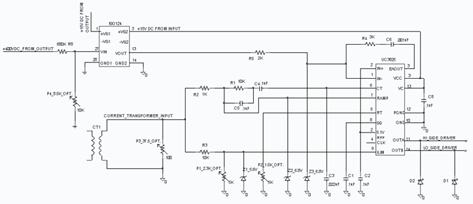
Overall, this circuit exemplifies a well-designed battery management system that incorporates essential features for safe and efficient charging, ensuring longevity and reliability of the rechargeable battery.10 hours using the constant current charging, use more convenient, the circuit shown in FIG. Electricity through the secondary transformer T stepped down, all the way from the rear VD1 rectifier, R1, C1 filtering, VD4 regulated by R2, C2 secondary filter output 4.6V regulated voltage control circuit for four; another route VD2 It provides four half-wave rectified pulse current for charging. Only one is shown the way in which the control circuit, the remaining three are the same way. Control manifold with four comparator LM339, its non-inverting input voltage 1.46V to stabilize, which is on the R3, the power indicator LED LED1 get 1.9V stabilized voltage by R4, R5 partial pressure provided by R12; and a comparator inverting input is reflected in the change in voltage of a rechargeable battery, since the input of the comparator does not consume current, R9, no voltage drop on R12, the comparator can truly reflect the comparison voltage size.
When charging the battery voltage is low, the potential of high-inverting input terminal, a control MOSFET V1, the charging circuit is formed. At the same time charging indicator light emitting diode LED2 lights; When the rechargeable battery voltage reaches 1.46V, the comparator output low potential, V1 off, cut off the charging circuit and the battery voltage begins to fall, due to VD3, R11 branch influence, more has a certain hysteresis, comparator avoid oscillation state.
Only the battery voltage drop is large, and the output of the comparator was a high potential so that V1 conduction, charging resumes. Such state of charge of the battery is intermittent, LED2 blinking, the battery is charged with the increase in intermittent time getting longer, LED2 blinking with increasing frequency is low, keeping the last in a long time off status indicates battery is fully charged.
R10 comparator output load resistance. Out of control when the battery is bad R8 prevented. R4 Adjustable Quad voltage comparator threshold comparator can also be fine-tuning their own based on the age of the battery being charged. Charge current with the charging voltage increases and decreases, the measured maximum of 110mA, the current size by changing R6 to fine-tune.
Related Circuits
The circuit is designed to operate with an audio power amplifier that uses 18V-0V-18V power rails. The specific voltage is not critical, but the feedback is referenced to an LED chain connected to a 12V rail, necessitating a separate...
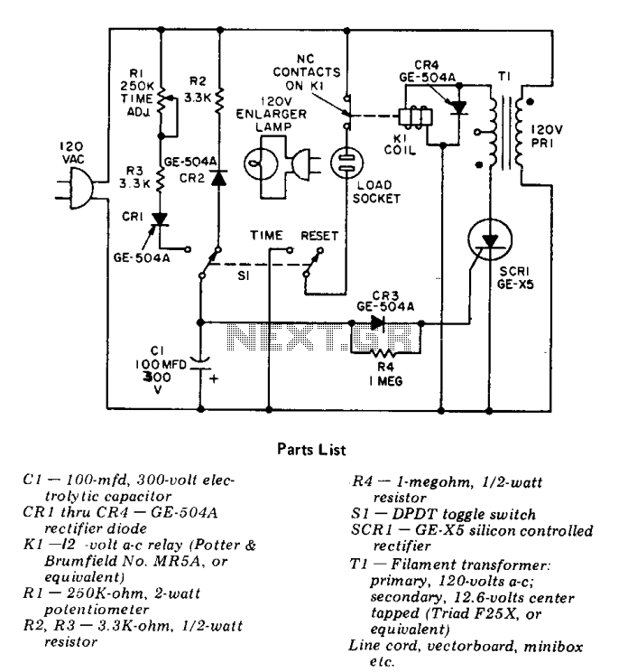
This precision solid-state time delay circuit features both delayed off and delayed on switch functions, which can be interchanged by simply swapping the relay contacts. The described time delay circuit is designed to provide precise control over the timing of...
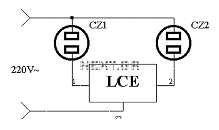
The application circuit operates the device as illustrated below. It is designed for cooling electrical equipment, typically utilizing a cooling fan to dissipate heat. The LCE employs a synchronous control socket on the device and its connections remain unchanged....
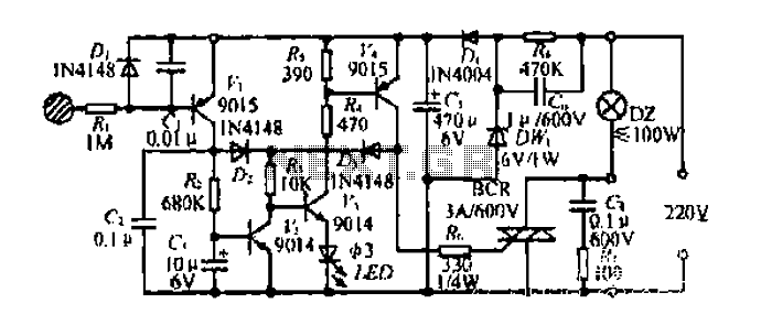
Diagram 2 depicts a shake tube circuit with a capacitance (C) and a trigger voltage rectifier filter element. The circuit includes a trigger voltage transistor amplifier (H), three pull tubes (n, U, v), and utilizes a thyristor as a...
The UC3825 IC, manufactured by Texas Instruments, is a high-speed pulse width modulation (PWM) controller that serves as the central processor for a DC/DC converter control circuit. This circuit primarily consists of three integrated circuits: the UC3825BN, ISO124, and...

This design schematic illustrates a Crystal Colpitts oscillator that can be implemented using a transistor and a parallel mode crystal. In this circuit, the crystal functions as an inductance. A large value capacitive divider is utilized between the gate,...