
High-voltage-inverter

The circuit converts a DC voltage (V+) into a high-amplitude square wave within the audio frequency range. The dual timer, IC2, serves as a cost-effective alternative to traditional transformers for providing complementary base drive to the power transistors, Q1 and Q2. This setup allows for the conversion of a 6 to 12 V battery output into an AC amplitude, primarily limited by the power rating of transformer T1. Timer IC1 is configured as an oscillator to generate a symmetrical square-wave drive to both inputs of IC2. The timing components, R2 and C1, produce an output frequency of 2.2 kHz. By connecting half of IC2 in inverting mode and the other half in non-inverting mode, the outputs of the timer alternately drive the two transistors. The audio-output transformer, T1, can be operated as a step-up transformer by connecting it in reverse, using the output winding as an input. The transformer delivers an output voltage across the load resistor RL of 4 x N x V+ Vpk-pk, where N is the transformer turns ratio. For the circuit illustrated, the output swing is 100 x V+ Vpk-pk.
The described circuit utilizes a dual timer integrated circuit (IC) to generate a square wave output from a direct current (DC) voltage source. The circuit's primary function is to convert a low DC voltage into a high-amplitude square wave, which can be used for various audio applications. The dual timer, identified as IC2, offers a straightforward and economical solution for driving power transistors Q1 and Q2, which are crucial for amplifying the output signal.
To initiate the oscillation, timer IC1 is configured with specific timing components, R2 and C1, which establish a frequency of 2.2 kHz. This frequency is suitable for audio applications, enabling the generation of sound waves in the audible range. The symmetrical square wave produced by IC1 is fed into the dual timer IC2, where the inverting and non-inverting outputs are utilized to control the switching of the transistors alternately. This arrangement ensures that both transistors are driven effectively, allowing for efficient amplification of the signal.
The transformer T1 plays a significant role in the circuit by acting as a step-up transformer. When connected in reverse, it can transform the low voltage square wave into a higher voltage AC signal suitable for driving speakers or other audio devices. The output voltage across the load resistor RL can be calculated using the formula 4 x N x V+ Vpk-pk, where N represents the turns ratio of the transformer. This means that the output voltage can be significantly increased, depending on the transformer design.
In summary, the circuit is designed to convert a low DC voltage into a high-amplitude square wave using a dual timer IC and power transistors, with the transformer providing the necessary voltage amplification for audio applications. The careful selection of timing components and transformer specifications ensures optimal performance and efficiency in converting and amplifying the input signal.The circuit converts a de voltage (V +) to a high-amplitude square wave in the audio-frequency range. The dual timer, IC2, provides an inexpensive alternative to the traditional transformer for providing complementary base drive to the power transistors, Ql and Q2.
You can convert a 6 to 12 V battery output, for example, to an ac amplitude, which is limited primarily by the power rating of transformer Tl. Connect timer IC1 as an oscillator to provide a symmetrical square-wave drive to both inputs of IC2.
The timing components, R2 and Cl, produce a 2.2-kHz output frequency. By connecting half of IC2 in the inverting mode and the other half in noninverting mode, the timer"s outputs alternately drive the two transistors. You can operate the audio-output transformer, Tl, as a step-up transformer by connecting it backwardsusing the output winding as an input.
The transformer delivers an output voltage across RL of 4 x N x V+V pk-pk, where Nis the transformer turns ratio. For the circuit shown, the output swing is 100 x V+V pk-pk.
Related Circuits
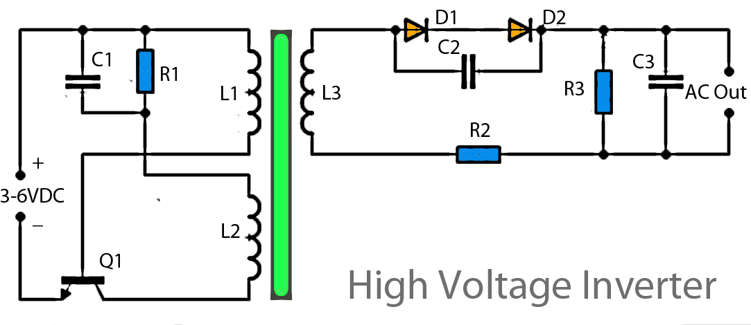
This inverter circuit operates using a transistor and transformer, along with other components, to elevate the voltage. The input supply voltage ranges from 3V to 6V DC, which is then converted to a high voltage AC output. However, the...