
High Voltage Joule Thief Circuit

The circuit in question is a voltage step-up converter, commonly referred to as a boost converter. This type of circuit is designed to increase the voltage from a low input level to a significantly higher output level. The core components of the circuit typically include an inductor, a switch (often a transistor), a diode, and a capacitor.
The operation begins when the switch is closed, allowing current to flow through the inductor. During this time, energy is stored in the magnetic field of the inductor. When the switch opens, the inductor resists the change in current, causing the voltage across it to increase. This higher voltage is then directed through the diode to the output capacitor, which smooths the output voltage and provides a steady 120 volts.
Key considerations in the design of such a circuit include the selection of appropriate components to handle the power levels involved, ensuring that the transistor can switch rapidly and efficiently, and that the diode can withstand the reverse voltage. Additionally, the inductor must be chosen to meet the energy storage requirements without saturating.
The circuit may also incorporate feedback mechanisms to regulate the output voltage, ensuring stability under varying load conditions. This can be achieved using operational amplifiers or dedicated voltage regulator ICs that monitor the output voltage and adjust the duty cycle of the switching element accordingly.
Overall, the described circuit is a practical solution for applications requiring a compact and efficient method to convert low voltage to a much higher voltage, suitable for powering devices that operate at 120 volts.Anyone who wants the circuit diagram, it is right here in the description. This little circuit takes in 1.5 volts and puts out 120 volts. 🔗 External reference
Related Circuits

ECL integrated circuit non-saturated digital logic circuits. CMOS and ECL interface circuit shown in cross. ECL (Emitter Coupled Logic) integrated circuits are designed to operate in a non-saturated mode, providing high-speed digital logic functionality. These circuits are characterized by their...

This circuit is simple and inexpensive, which is its primary advantage. Although the output power is not high, the audio quality is good due to the TDA1910's low noise characteristics. This circuit is suitable for use as a student...
In this circuit, the SP6126 is configured as a Zeta converter to supply 0.3A for driving four series-connected LEDs. The SP6126 is a flexible and economical controller that provides the necessary functions required by a Zeta regulator. This report...
In electronic technology, the triode utilizes a variety of general components and parts. The parameters of the triode and numerous electrical parametric measurement schemes are closely related to measurement results. Therefore, in electronic design, the base pin, typological judgment,...
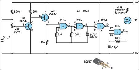
This design integrates power-on and low-battery indications, capable of operating with any battery voltage up to 15V. It features a very low current drain of 2mA or less and costs less than $3.50 with new components. When the battery...

The versatile circuit can be employed to achieve various functions, including an astable multivibrator, a monostable multivibrator, a switch debouncer, or a frequency discriminator. Inverters U1a and U1b are configured as a latch. When the input voltage (VIN) is...