
Low Cost Battery Condition IndicatorCircuit
This circuit design is an effective solution for indicating both power-on status and low battery conditions in battery-operated devices. The use of a 4093 CMOS quad Schmitt NAND allows for efficient operation with minimal power consumption, making it suitable for applications where battery life is critical. The oscillator design, which operates at a frequency of at least 50Hz, ensures that the LED appears continuously lit to the human eye while actually drawing significantly less current than a conventional LED setup.
The choice of a series resistor or a combination of a fixed resistor and trimpot for LED current limiting provides flexibility in adapting to various battery voltages. The low-battery indication mechanism, which causes the LED to pulse at about 1Hz, is a clear and effective way to alert users to the need for a battery replacement.
Transistor Q1 plays a crucial role in monitoring the battery voltage. By using a trimpot (VR1), precise calibration is achievable, allowing the circuit to be fine-tuned to activate the low-battery indicator at the desired voltage threshold. The transition from the LED being continuously lit to pulsing at 1Hz is managed through the activation of Q2, which triggers the 2-gate oscillator when battery voltage falls below the specified threshold.
Overall, this design exemplifies a well-thought-out approach to battery management in electronic devices, balancing performance, cost, and power efficiency. The components selected are readily available, and the circuit can be easily implemented in various applications requiring reliable power management indicators.This design combines power-on and low-battery indication, can operate with any battery voltage up to 15V, has very low current drain (2mA or less) and costs less than $3. 50 with new parts. When the battery voltage is above a predetermined minimum, power on is indicated by what appears to be a steadily lit LED.
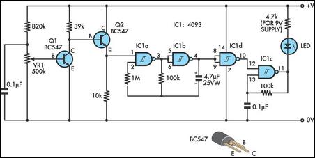
In fact, the LED is being pulsed by a free-running relaxation oscillator formed by IC1c, one gate of a 4093 CMOS quad Schmitt NAND. The frequency of this oscillator should be at least 50Hz, so that it appears to be continuously on while at the same time drawing far less average current than a steadily lit LED. The series resistor for the LED needs to be selected for each battery voltage, to limit the current to a safe vale or you could use a fixed resistor and a series trimpot for flexibility.
Low battery voltage is indicated by the LED pulsing at around 1Hz. The battery voltage is monitored by transistor Q1 and trimpot VR1. Once the voltage at its base falls below 0. 6V, Q1 turns off and Q2 turns on to enable the 2-gate oscillator formed by IC1a and IC1b, which runs at 1Hz. The pulses from this oscillator are inverted by IC1d to gate the LED oscillator on and off. Calibration can be done with a variable bench power supply set to the lowest battery voltage you will accept.
Power up the circuit and adjust VR1 until the LED pulses once per second. Author: Peter Wilson - Copyright: Silicon Chip 🔗 External reference
Related Circuits
This circuit utilizes the widely available and user-friendly LM3914 integrated circuit (IC). The LM3914 is straightforward to operate, does not require external voltage regulators due to its built-in voltage regulation, and can be powered by nearly any voltage source....

The 1B32 application circuit features multiple pressure sensors as illustrated in the figure. Excitation power is supplied through the AD542, which is followed by a TIP32 transistor that drives multiple bridge sensors. The AD542 operates as a Bi-FET in...
The high and low voltage cut-off with delay and alarm circuit, along with its circuit diagram, is explained in this post. The high and low voltage cut-off circuit is designed to protect electrical devices from damage caused by excessive voltage...
A battery voltage indication circuit that changes the status display. When the battery voltage is normal, an additional transistor drives an LED, which remains off. However, if the battery voltage falls below a critical threshold, the LED begins to...
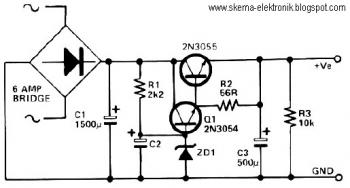
This circuit can be utilized in applications requiring high current and low ripple voltage, such as in high-powered Class AB amplifiers where high-quality audio reproduction is essential. Q1 and Q2, along with resistor R2, function as a power Darlington...

A display tube utilizing a constant current circuit to ensure a steady flow through the tube. The display tube operates on the principle of maintaining a constant current to achieve consistent brightness and performance. The circuit typically comprises a current...