
His Masters Noise: A Thoroughly Modern Tube Phono Preamp
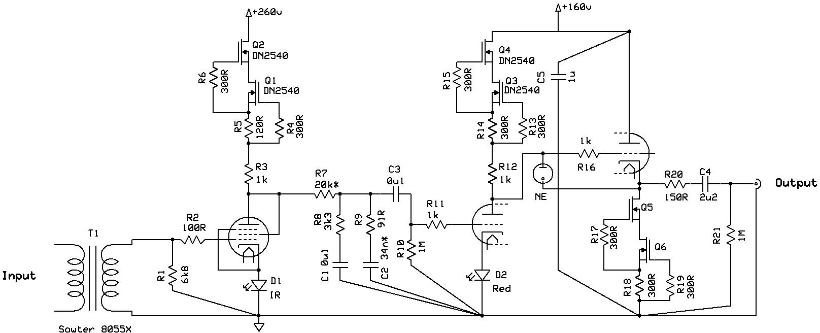
The circuit design under consideration features a configuration that includes several transformers, which are essential for voltage transformation and isolation in power supply applications. Transformers play a critical role in stepping up or stepping down AC voltages, ensuring that the output voltage meets the required specifications for the load. The presence of "almost enough" transformers suggests a design that is close to optimal but may require additional transformers to enhance performance or provide redundancy.
However, the mention of "certainly not enough shunt regulators" indicates a potential limitation in the circuit's ability to manage voltage levels effectively. Shunt regulators are vital components in maintaining a stable output voltage by diverting excess current away from the load, thus protecting sensitive components from overvoltage conditions. An insufficient number of shunt regulators could lead to voltage fluctuations, which may adversely affect the performance and reliability of the overall circuit.
In a comprehensive design, it is crucial to evaluate the specifications and requirements of the load to determine the optimal number of transformers and shunt regulators needed. This evaluation ensures that the circuit can handle variations in input voltage and load conditions while providing a stable and reliable output. Additionally, the layout and interconnections of these components should be designed to minimize electromagnetic interference and ensure efficient power distribution.
Overall, while the existing design has a solid foundation with its transformers, careful consideration must be given to augmenting the number of shunt regulators to achieve a robust and reliable circuit performance.even if I didn`t read thoroughly nice one almost enough xformers , but certainly not enough shunt regs.. 🔗 External reference
Related Circuits
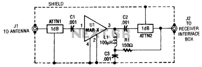
The MAR-x preamplifier is designed to operate within a frequency range of up to 1.5 or 2 GHz, depending on the selected MAR-x integrated circuit (IC). For applications requiring a low noise figure, ATTN1 should be omitted. Both ATTN1...
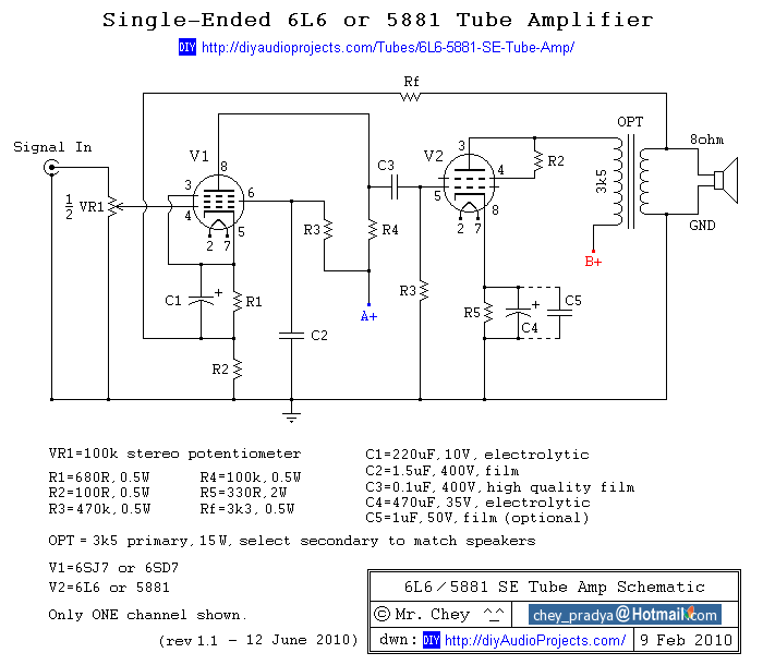
This past summer, an inspiration arose from watching "Transformers: Revenge of the Fallen" to construct an enclosure for a vacuum tube amplifier featuring the Decepticon logo. The tube amplifier replaces a solid-state amplifier that was driven by a tube...
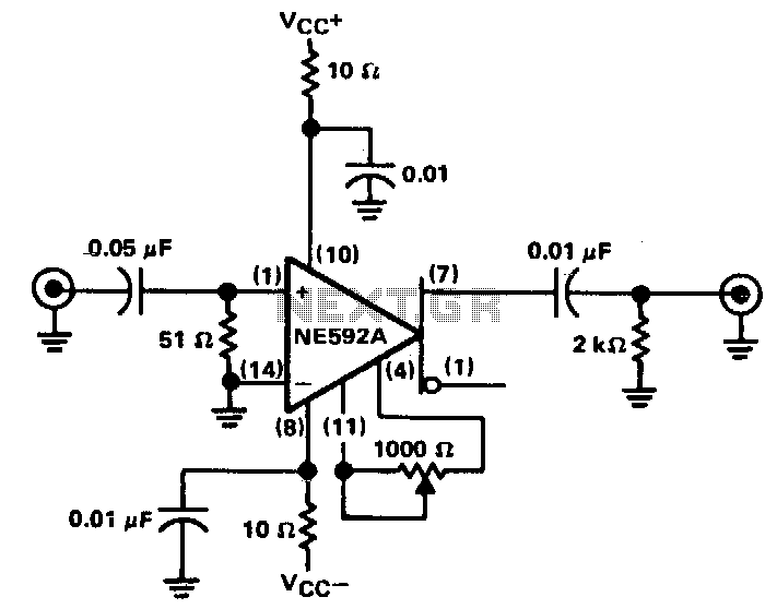
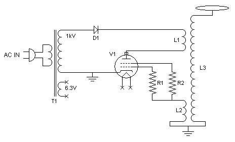
The circuit provides a voltage gain of 20 ±0.1 dB within a frequency range of 500 kHz to 50 MHz. The low-frequency response of the amplifier can be enhanced by increasing the value of the 0.05 µF capacitor connected...
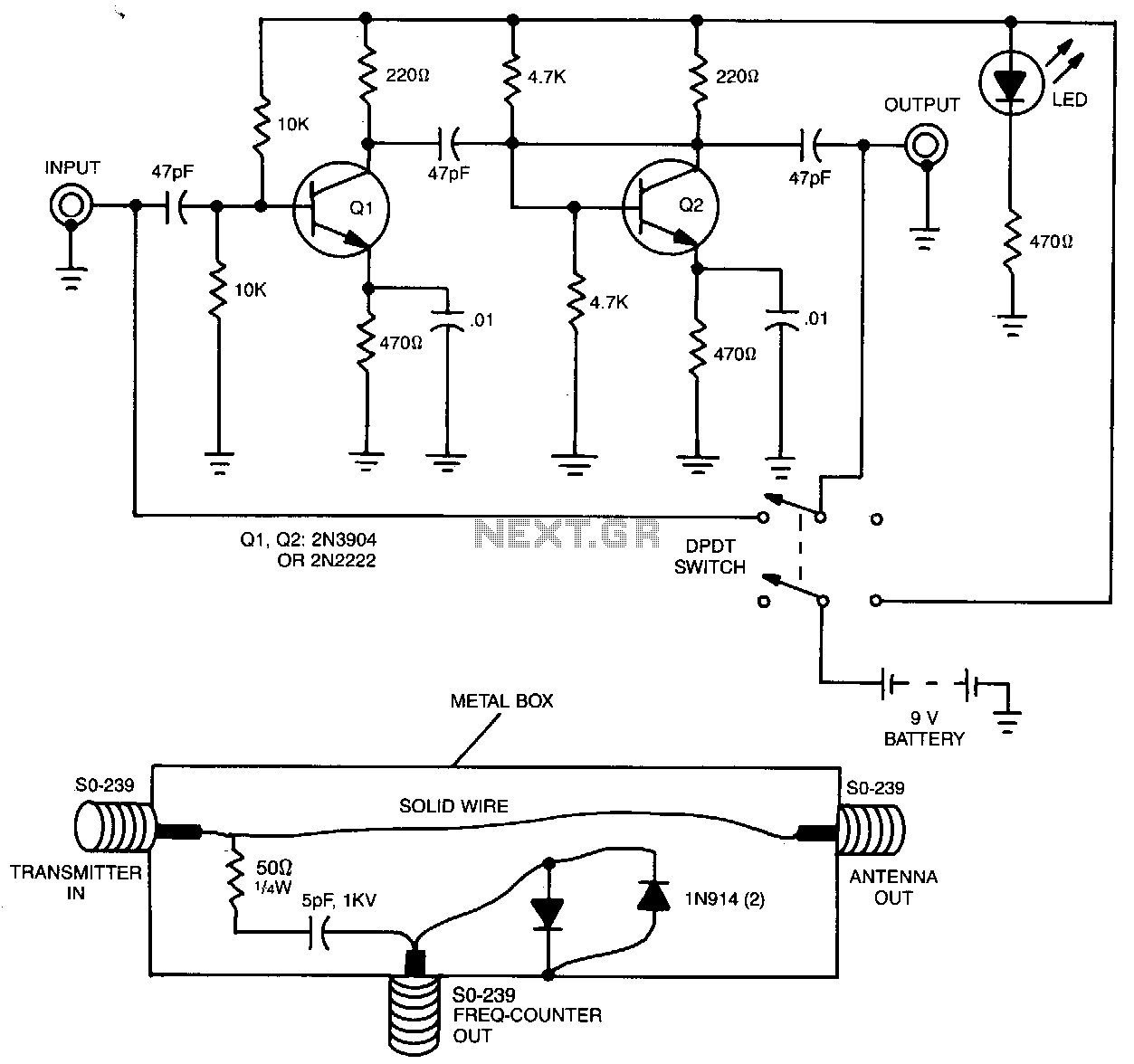
The preamplifier, when utilized with a short length of shielded cable and clip leads, allows signals that typically do not produce a readout to generate precise and stable readings on the counter. A DPDT switch is incorporated to bypass...
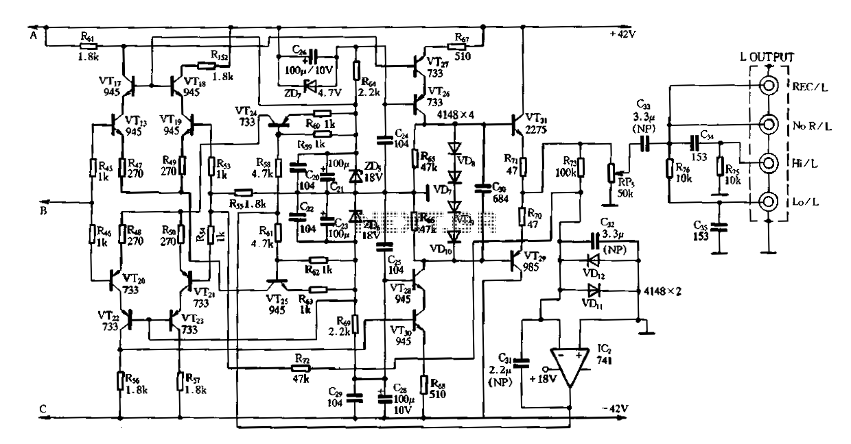
Figure 3-2 (b) represents the second half of the circuit, where transistors VT17 to VT31 are configured as power amplifiers and pre-amplifiers. This section is structurally identical to the operational integrated circuit IC2 and includes zero servos. The circuit...
This tube Tesla coil was constructed within a CPU power supply unit. Initially, it was assembled on a workbench using various components and jumpers for connections. The tube utilized is a 4X150 transmitting tube that employs forced air cooling....