
Motor control circuit for forward and reverse phase induction
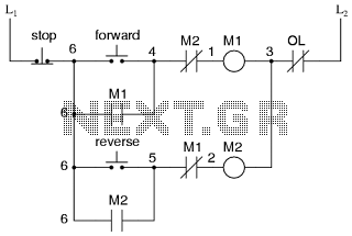
The described power diagram illustrates a basic control system for a DC motor, enabling forward and reverse operation through polarity reversal. The motor is connected to a power supply, typically a DC source, and is controlled using a switching mechanism, such as a relay or an H-bridge circuit.
In the forward operation mode, the positive terminal of the power supply is connected to terminal R of the motor, while the negative terminal is connected to terminal S. This configuration allows the motor to rotate in one direction. To reverse the direction of the motor, the connections are altered: terminal R is connected to the negative terminal of the power supply, and terminal S is connected to the positive terminal. This reversal of polarity causes the motor to rotate in the opposite direction.
The H-bridge configuration is particularly effective for this purpose, as it allows for efficient switching of the motor terminals without the need for mechanical relays, which can introduce wear and tear over time. An H-bridge consists of four switches (transistors or MOSFETs) arranged in a bridge configuration, enabling control over the direction and speed of the motor by varying the duty cycle of the PWM (Pulse Width Modulation) signals applied to the switches.
In addition to the polarity switching, the circuit may include protection features such as diodes to prevent back EMF (Electromotive Force) from damaging the control circuitry when the motor is turned off. Proper sizing of components, including the power supply and switching devices, is crucial to ensure reliable operation under varying load conditions.
This power diagram serves as a fundamental reference for understanding the basic principles of motor control and can be expanded upon with additional features such as speed control, feedback systems, and safety mechanisms for enhanced performance and reliability.This is the Power diagram off Motor forward reverse, to change the motor direction we must change the one polarty for example R to S, for detail please see below: 🔗 External reference
Related Circuits
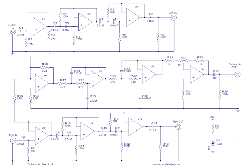
This is the schematic diagram of an operational amplifier (op-amp) based subwoofer filter. Audio frequencies below 200 Hz are typically categorized within the subwoofer range, indicating that a subwoofer filter should have a cutoff frequency around 200 Hz. The...
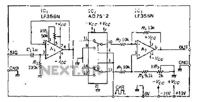
An analog switch (double loop, double-break) and a differential modulation amplifier are used in this circuit. The carrier control switch operates by switching contacts at specific times, inverting the input modulation wave. When the next carrier signal is applied...
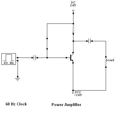
The function of a DC to AC inverter is to convert Direct Current (DC) voltage into Alternating Current (AC) voltage. These inverters are commonly employed to convert High Voltage DC (HVDC) transmission voltage back to AC and to change...
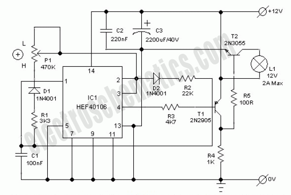
This electronic lighting dimmer circuit is designed to control the brightness of incandescent lamps, but it is not suitable for fluorescent lamps. It operates with both 110V and 220V AC power sources. The circuit is connected in series with...
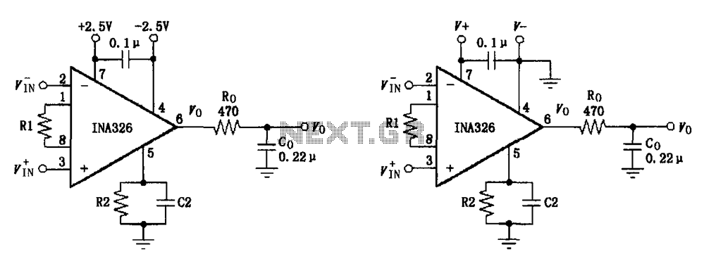
The basic connection circuit for the INA326/327 includes signals and power. A 0.1 µF capacitor is selected for power supply filtering and should be placed as close to the chip's supply pin as possible. Ro and Co serve as...
Firecrackers are typically ignited using a matchstick or candle. After igniting the fuse, it is necessary to retreat quickly to a safe distance. This method poses safety risks due to the possibility of the firecracker detonating before reaching a...