
Homebrew RF Test Equipment and Software
The described projects provide a comprehensive approach to building RF design test equipment, emphasizing practical applications of electronic skills in a home laboratory setting. The modifications to the iwconfig command enhance usability for wireless network diagnostics, allowing for real-time monitoring of signal strength through visual and auditory feedback. The integration of pinger.pl as a signal meter exemplifies a straightforward approach to antenna alignment, crucial for optimizing wireless communication.
The National LMX2240 Intermediate Frequency Receiver's RSSI Out pin serves as a vital component in assessing signal quality. Utilizing a modulation meter to interpret the RSSI output transforms voltage spikes into a usable metric for signal strength, allowing technicians to evaluate antenna performance effectively. The Mark Weiss modulation meter serves as a practical tool for field strength verification, reinforcing the importance of accurate signal assessment in RF design.
The ability to create attenuator pads for simulating signal loss is crucial for ensuring reliable wireless network performance. The option to purchase commercial attenuators or repurpose high-loss cables offers flexibility in testing scenarios, accommodating various power levels and frequency ranges. The inclusion of a homebrew cable reflection tester schematic provides a valuable resource for diagnosing coaxial cable integrity, ensuring that installations are free from shorts and impedance mismatches.
Overall, these projects and techniques equip engineers and technicians with the necessary tools and knowledge to conduct thorough RF testing and validation, fostering a deeper understanding of wireless communication systems.This section will list several projects which will allow you to build your own RF design test equipment. Microwave construction techniques and basic electronic skills will be required on some projects, but the tools you can make will equal what the so-called "professionals" use.
We modified the iwconfig command included with Jean Tourrilhes` Wirele ss Tools for Linux slightly to help with the wireless link setup and alignment. Here is what the original output of the command iwconfig eth1 would look like: Here is a screen shot of the modified version. It displays the same information, just with some lame ANSI colors and a bar graph for signal strength.
I`m not sure if it`s entirely accurate, so use at your own risk. You can pick this version up here. There is also a version for the 915 MHz WaveLANs. It also includes the perl script pinger. pl, ( screen shot ) you can use this as a signal meter to help align the antennas in your network. It`s just a wrapper around the ping command to display the millisecond output with an ANSI bar graph. It also has an option for using the `say` command from the rsynth package to speak the ping millisecond value to you.
That`s useful for when you`re hanging from a tower trying to align antennas. Another method of testing the received signal strength on a Symphony based wireless network is with a homebrew signal meter. The National LMX2240 Intermediate Frequency Receiver has a certain pin called "RSSI Out". RSSI stands for relative signal strength indicator and supplies a voltage output that is an indication of the received signal strength.
On a weakly received signal the voltage output of the RSSI is small and on a strong signal it`s large. Unfortunately, this output is only on during the receive portion and off during transmit. This makes the RSSI output look like a series of spikes. To average out these spikes you can use a very common piece of test equipment on any good technician`s bench: a modulation meter.
What You say Modulation meters convert received audio signals into a DC voltage indication of modulation, if you input the RSSI spikes into the meter (and readjust its ballistics) you will get a poor man`s signal meter. The meter I use is based on the Mark Weiss modulation meter. This is a simple field strength meter that can be used to verify that you antenna is in fact radiating energy.
It`s based on one from the ARRL UHF/Microwave Projects Manual, Volume 1 and can be used from 30 MHz to well over 2 GHz if properly constructed You can also make some attenuator pads to help simulate real life signal loss when testing your wireless network links. If you wish, you can order commercial inline attenuators from Mini-Circuits that will handle 2 Watts of power, DC - 18 GHz, and have built in SMA connectors for around $37 a piece.
You may also combine attenuator pads to increase the overall attenuation. It`s also possible to use a long length of high-loss cable, such as RG-174, as an attenuator. Higher wattage resistors will handle higher RF power, though the frequency response will suffer due to parasitic reactances. Lower wattage resistors will handle higher power if applied in small durations (milliseconds), like which is commonly found in most wireless network applications.
Here is a schematic for a homebrew cable reflection tester from the December 1996 issue of Electronics Now. It`s very useful for checking coax cable runs for shorts or even impedance mismatches. It works by sending a pulse down the cable, then checking the return signal on an oscilloscope. You can then determine the distance to a short or impedance mismatch using simple distance = time x speed equations.
Be sure to divide your time by 2, and take in account your cable`s velocity factor. Here is a schematic for a homebrew cable reflection tester from the December 1996 issue of Electronics Now. It`s very useful for checking coax cable runs for shorts or even im 🔗 External reference
Related Circuits
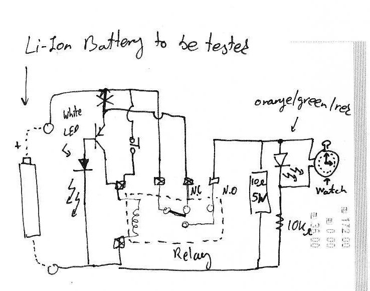
It is assumed that individuals interested in constructing this circuit can interpret the schematics provided below. Basic principles: Note that lithium-ion batteries should not be discharged below 3V. The circuit design focuses on the safe operation of lithium-ion batteries, particularly...
This compact circuit is designed to verify the basic functionality of an infrared remote control unit. It operates on the straightforward principle of connecting a piezo buzzer directly to an infrared (IR) receiver integrated circuit (IC). This approach is...
This document describes a simple 2.4 GHz SWR meter that utilizes surplus microwave hardware. The main component is a MECA -20/-20 dB Directional Coupler, which operates within a frequency range of approximately 700 MHz to 2.5 GHz. This directional...

This device functions as a convenient tool for testing infrared (IR) remote control transmitters used with televisions, VCRs, and similar devices. The IR signals emitted from a remote control are detected by the IR sensor module within the tester,...
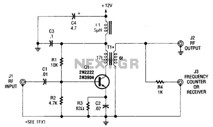
This single-stage amplifier, utilizing a 2N2222 or 2N3904 general-purpose transistor, is designed for interfacing with test instruments. The transformer T1 is an Amidon Associates FT-23-43 core, wound with 17 turns of #26 wire for the primary and 6 turns...
This is a convenient design for a transistor tester. The advantage of this circuit is that transistors can be tested without actually doing the circuit soldering. The tester uses two ICs: an NE 555 timer and a CMOS IC...