
Transistor tester schematic
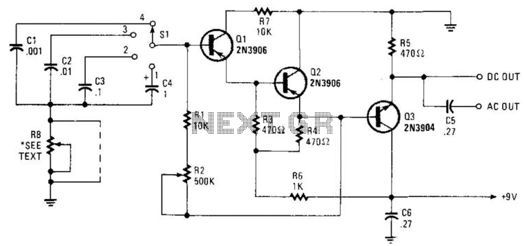
The transistor tester circuit is designed to facilitate the testing of both NPN and PNP transistors without the need for soldering, making it a practical tool for electronics enthusiasts and professionals alike. The core of the circuit consists of an NE 555 timer configured in astable mode, which produces a continuous square wave output at approximately 12 Hz. This frequency is suitable for testing the switching characteristics of transistors.
The NE 555 timer's output is fed into a CMOS IC 4027, which contains two D-type flip-flops. These flip-flops are utilized to latch the output signals based on the square wave generated by the timer. When a transistor is connected to the tester, the type of transistor determines which indicator LED (D5 for NPN and D6 for PNP) will illuminate during the testing process. The circuit is designed to ensure that the correct LED lights up, providing a clear visual indication of the transistor's functionality.
For proper operation, it is critical to connect pins 1 to 9 of the CMOS IC 4027 to ground, establishing a stable reference point for the flip-flops. This grounding ensures that the circuit functions correctly and that the output signals are reliable.
Overall, this transistor tester circuit is an efficient and user-friendly solution for quickly assessing the operational status of transistors, making it an invaluable addition to any electronics toolkit.This is a convenient design for a transistor tester. The advantage of this circuit is that transistors can be tested without actually doing the circuit soldering. The tortester uses two ICs: an NE 555 timer and a CMOS IC 4027. In 4027 there are two flip-flops. The timer generates a square wave of about 12 Hz. IC2 through the square wave then used to test the transistor. Depending on the type of transistor (NPN or PNP) light during testing D5 or D6. When building, make sure that pin 1 to 9 of IC2 are connected to ground. 🔗 External reference
Related Circuits
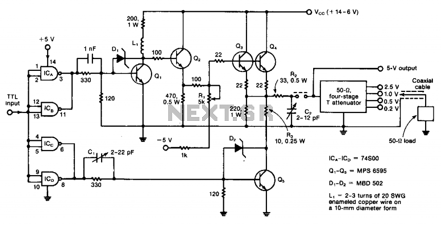
The circuit operates from DC to 50 MHz and is capable of delivering pulses as short as 10 ns. It is driven by a TTL signal through a 740S00 quad Schottky NAND gate, with input connections made via ICA...
Seven narrow pulses ranging from 2 Hz to 50 kHz are generated by this circuit. Capacitors C1 through C4 provide frequency ranges in decode steps. Resistors R1 and R2 regulate the charging time of capacitors C1 through C4. R2...
I designed a simple sinewave generator based on a Analog Devices AD9832 chip. It will generate a sinewave from 0.005 to 12 MHz in 0.005 Hz steps. That's pretty good, and definitely good enough for me! But while waiting...
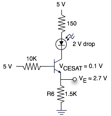
The schematic represents a relatively simple transistor circuit. Analyzing such schematics evokes memories of college days spent studying electrical engineering. However, the complexity of the schematic can be daunting after a long time away from the subject. To refresh...
This is a simple and easy-to-build gold detector circuit. The circuit is capable of sensing gold, metal, or coins from a distance of approximately 20 cm, depending on the size of the object being detected. It oscillates at around...

The complete hardware schematic of the Night Light Saver V6.0 includes an AC line protected by a 1A fuse (F1). Any short circuit caused by the components of the saver will blow the fuse. Resistor R1 and capacitor C1...