
Homemade GSM Car Security System

The homemade GSM car security system employs a simple yet effective circuit design that integrates a GSM module, microcontroller, and various sensors to enhance vehicle security. The primary components of the circuit include a GSM module, which facilitates communication via SMS, a microcontroller to process signals and manage the system, and sensors such as motion detectors or door sensors to detect unauthorized access.
The GSM module, typically an SIM800 or similar, is responsible for sending alerts to the vehicle owner via SMS when a security breach is detected. The microcontroller, often an Arduino or PIC, serves as the central processing unit, interpreting signals from the sensors and executing predefined actions based on the input received.
When a sensor is triggered, the microcontroller activates the GSM module to send a notification message to the owner's mobile phone, providing real-time updates on the vehicle's status. Additionally, the system can be designed to include features such as remote engine immobilization, allowing the owner to disable the vehicle's ignition through an SMS command.
Power supply considerations are crucial for this circuit, as it must operate reliably in various conditions. A stable voltage regulator can be employed to ensure that the microcontroller and GSM module receive the appropriate voltage levels. Furthermore, the circuit can be enhanced with backup battery solutions to maintain functionality during power outages or when the vehicle is parked.
Overall, this homemade GSM car security system provides an accessible approach to vehicle protection, leveraging modern communication technology to deliver timely alerts and control features to the owner.This Homemade GSM Car Security System super simple circuit design of a GSM car security system really works.. 🔗 External reference
Related Circuits
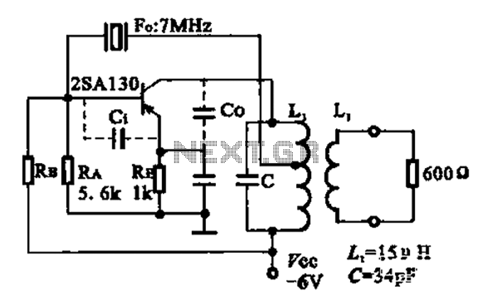
The 2SA130 transistor is used in an oscillator circuit with an oscillation frequency of 7 MHz. The power supply voltage is 6V, and the load is a frequency-selective resonant circuit with a quality factor of 600. The circuit utilizes the...
We have developed a powerful yet inexpensive and easy to construct experiment control system. The construction of the system together with the control software is described here. All circuits and software are free to download and use for nonprofit....
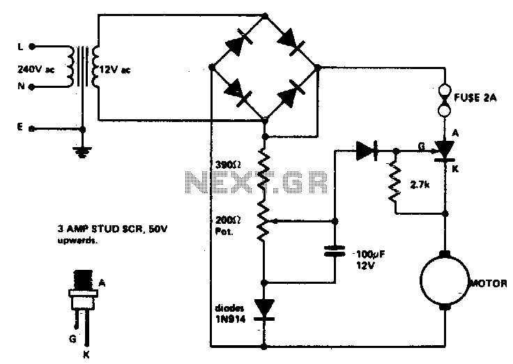
Low voltage speed control provides excellent starting torque and effective speed regulation. Additionally, a reversing switch can be integrated into the motor leads. Low voltage speed control circuits are essential in applications where precise motor control is required, such as...
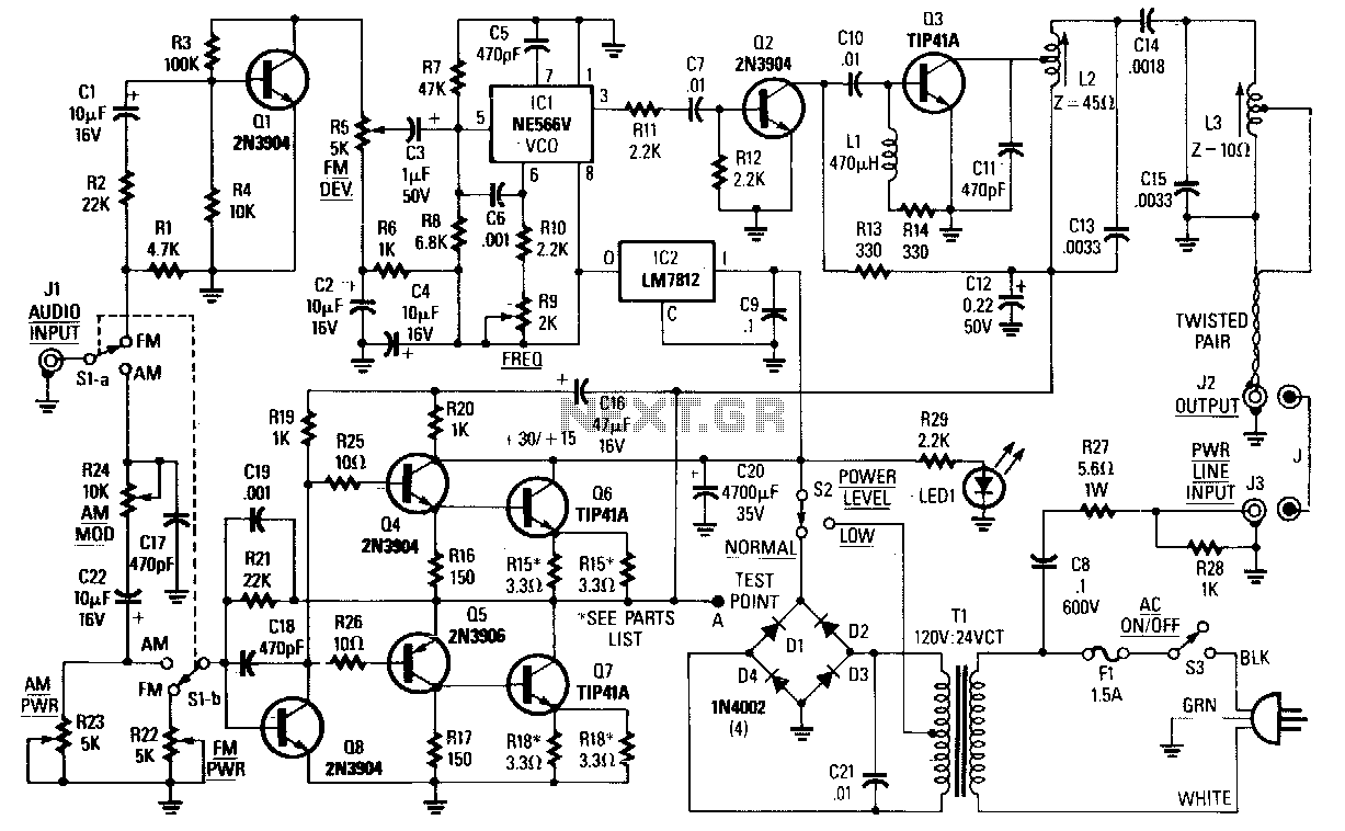
The choice between AM, narrowband FM (less than 15 kHz), or wideband FM (greater than 30 kHz) is determined by the specific application. FM is preferable for music transmission due to its superior noise immunity. For speech or other...
Many modern intercom units are now equipped with video cameras, allowing users to see and hear who is at the door. However, the positioning of the camera lens often serves as a support point for individuals during conversations, resulting...
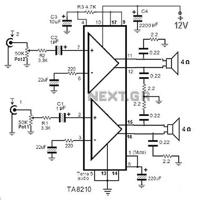
This circuit consists of a 2 x 22 watt BTL amplifier utilizing the IC TA8210AH. It functions not only as an automobile amplifier but is also suitable for low-frequency sound applications, particularly in high-fidelity audio systems, due to its...