
Video Switch for Intercom System
The proposed circuit design utilizes a dual-camera setup to enhance visibility in intercom systems. The implementation involves strategically placing two cameras at a distance from each other on the exterior of a building. This arrangement allows for the effective capture of video feeds, which are then alternated for display on a single monitor situated indoors. The video switch module is critical to this design, enabling the seamless transition between the two camera feeds without the need for extensive wiring.
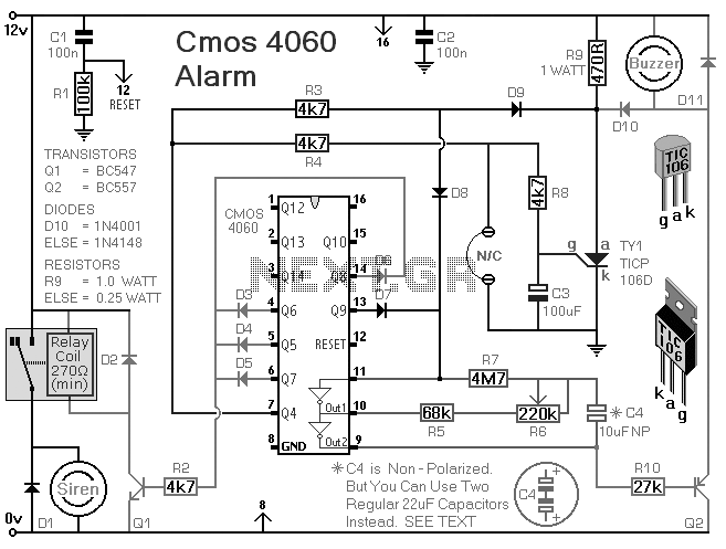
The core of the circuit is built around the 4060 integrated circuit (IC), which is known for its versatility in digital applications. In this configuration, the 4060 IC manages the signal switching through its internal logic gates. Specifically, switches IC2a and IC2d are responsible for selecting which camera feed is outputted based on control signals generated by IC2b and IC2c. These control signals are designed to be out of phase, ensuring that only one camera feed is displayed at any given time.
To address potential signal degradation over long distances, a video amplifier is incorporated into the circuit. This amplifier is capable of adjusting the brightness and contrast of the video signals independently, thus enhancing the overall quality of the video feed received at the monitor. The 555 timer IC serves as the timing mechanism for the switching process, producing a clock signal that dictates the frequency at which the camera feeds are alternated. The specified component values allow for a switching interval of approximately 2 seconds, providing a balanced view of both camera feeds.
This circuit design not only improves intercom functionality but also has broader applications in surveillance systems, where multiple cameras may be required but limited cabling infrastructure exists. The ability to alternate between camera feeds effectively maximizes visibility and enhances security monitoring capabilities.Nowadays a lot of intercom units are equipped with video cameras so that you can see as well as hear who is at the door. Unfortunately, the camera lens is perfectly placed to serve as a sort of support point for people during the conversation, with the result that there`s hardly anything left see in the video imagery.
One way to solve this problem is to install two cameras on the street side instead only one, preferably some distance apart. If you display the imagery from the two cameras alternately, then at least half of the time you will be able to see what is happening in front of the door. Thanks to the video switch module described here, which should be installed on the street side not too far away from the two cameras, you need only one monitor inside the house and you don`t need to install any additional video cables.
Along with a video switch, the circuit includes a video amplifier that has been used with good results in many other electronics projects, which allows the brightness and the contrast to be adjusted separately. This amplifier is included because the distance between the street and the house may be rather large, so it is helpful to be able to compensate for cable attenuation in this manner.
The switch stage is built around the well known 4060 IC, in which switches IC2a and IC2d alternately pass one of the two signals to the output. They are driven by switches IC2b and IC2c, which generate control signals that are 180 degrees out of phase.
The switching rate for the video signals is determined by a clock signal from an old standby` 555 IC, which causes the signals to swap every 2 seconds with the specified component values. Naturally, this circuit can also used in many other situations, such as where two cameras are needed for surveillance but only one video cable is available.
🔗 External reference
Related Circuits
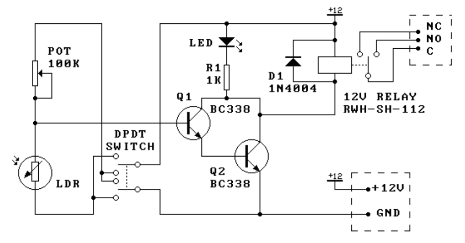
This kit is the most basic, practical circuit to build using an LDR to turn on a relay. The two transistors connected as a Darlington pair give the circuit enough sensitivity, while the trimpot gives sensitivity adjustment. The switching...
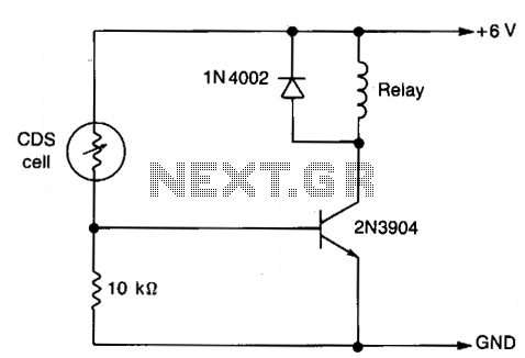
The resistance of the CDS cell decreases when exposed to light, activating the 2N3904 relay driver. The circuit utilizes a Cadmium Sulfide (CDS) photoresistor, which is a light-dependent resistor that changes its resistance based on the intensity of light...
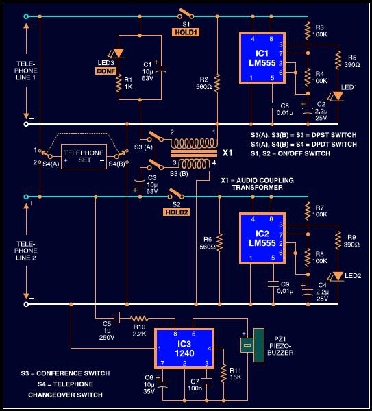
This is a simple circuit diagram of a duophone that enables access to two telephone lines through a single telephone set. Conversations on each line remain entirely private when the conference switch on the dual phone is off. Thus,...
This compact switching power supply utilizes a Schmitt trigger oscillator to control a switching transistor, which delivers current to a small inductor. While the transistor is activated, energy accumulates in the inductor, and upon deactivation, this energy is released...
Speaker relay delay controlling circuit for audio amplifier The speaker relay delay controlling circuit is designed to manage the connection between an audio amplifier and the connected speakers, ensuring that the speakers are activated only after a predetermined delay. This...
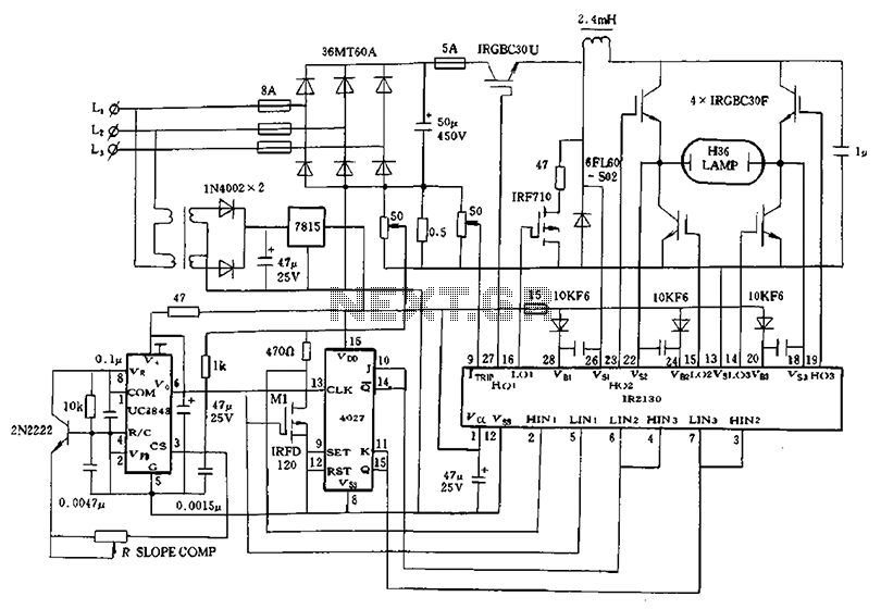
Application of a kilowatt high-pressure mercury lamp ballast system; the schematic in Figure 12.44 illustrates the IR213D used for a high-pressure mercury lamp ballast system. The IR2130 is utilized not only to drive a single-phase full-bridge inverter with four...
Warning: include(partials/cookie-banner.php): Failed to open stream: Permission denied in /var/www/html/nextgr/view-circuit.php on line 713
Warning: include(): Failed opening 'partials/cookie-banner.php' for inclusion (include_path='.:/usr/share/php') in /var/www/html/nextgr/view-circuit.php on line 713