
how to build cell phone controlled door

The electronic circuit described includes several essential components that work together to ensure the effective operation of the door locking mechanism. The NOKIA 1202 cell phone serves as the primary control unit, acting as a modem that receives calls and generates the specified ringtone. The tone amplifier circuit, composed of three transistors, amplifies the ringtone to a suitable level to activate the relay. The relay acts as a switch, connecting the power supply to the locking mechanism when triggered.
The CMOS flip-flop circuit is crucial for maintaining the state of the lock; it toggles between locked and unlocked states based on the input from the relay. This allows for a secure and reliable locking mechanism that can be controlled remotely. Additionally, the integration of a car central locking system with the manual locking shaft enhances the security and functionality of the door lock.
For practical implementation, it is important to ensure that the connections are secure and that the power supply is stable to avoid any interruptions in operation. Proper mounting of the components and the door lock mechanism is also necessary to ensure reliable performance. This project not only enhances security but also provides convenience, allowing users to control their door lock from virtually anywhere using their mobile phone.Controlling your door lock through your personal cell phone was never this easy. Learn how to build a simple electronic circuit that will help in converting your ordinary door lock into a high security door lock which can be now controlled through your own cell phone. Your ordinary door lock can be now very easily converted into a cell phone c ontrolled high security door lock. Learn the entire building procedure through some simple instructions and circuit schematics. A very simple configuration using a low cost cell phone (used as a modem) and an electronic circuit can be build to control remotely a high security door lock. Once the unit is built and attached to a door, by simply assigning your personal cell phone`s number inside the modem cell phone, you can alternately lock and unlock a particular door by sending subsequent miss calls through your cell phone to it from any part of the world.
We use a NOKIA 1202 as the modem cell phone here for the project. Let`s proceed and learn the simple instructions required to complete the project. The basic concept of the project is to detect a particular ringtone from a SIM supporting modem and use it to toggle the electronic circuit and the load (door lock) correspondingly. The very specific and unique ringtone Beep Once or the No Tone is available with every NOKIA cell phone.
And also this ring can be assigned to any particular fed number of the cell phone. So this ringtone becomes specific only to that particular number and will be sounded every time a call is received from the assigned number. This facility has been ideally exploited here. A 5 volt regulated supply is used to trickle charge the modem round the clock so that its battery is never discharged.
This supply also goes to the IC 4093 = pin 14 (+) and pin 7(-). An in-built cut-off system inside every NOKIA cell phone ensures a safe charging. The FIGURE above shows a simple three transistor amplifier circuit which is basically used as a tone amplifier. On receiving a miss call from the assigned number (owner`s cell phone), the modem immediately responds and produces the desired ringtone (Beep Once ).
This tone frequency is collected from the modem`s headphone socket and applied to the tone amplifier`s input. The ringtone is suitably amplified and is used to toggle a relay momentarily. This relay connects a 5 volt trigger pulse to the input of CMOS flip flop circuit and also sounds a buzzer.
The flip flop toggles in response to the above action and activates the following transistor/relay locking mechanism. A car central lock has been effectively integrated with an ordinary manual locking shaft to form an excellent door dead bolt.
The whole system activates in a push pull manner to alternately lock and unlock the door in response to every subsequent miss call from the owner`s cell phone. 🔗 External reference
Related Circuits

A telephone utilizes electric current to transmit sound information between homes. During a conversation, a steady electric current flows through both telephones, which share this current. As one person speaks into their telephone's microphone, the current drawn from the...
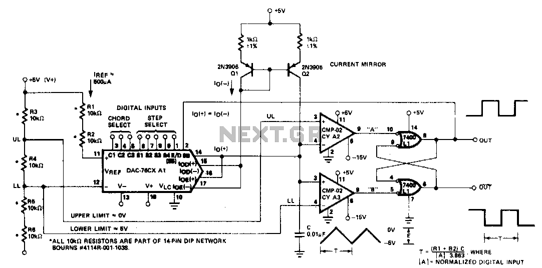
The microprocessor-controlled oscillator has a frequency range of 8159 to 1, covering from 2 Hz to 20 kHz. An exponential, current output integrated circuit digital-to-analog converter (DAC) functions as a programmable current source, alternately charging and discharging a capacitor...

Transistor Q1 functions as an amplifier for the condenser microphone MIC1. The output from Q1 is fed to the base of transistor Q2 through a 4.7 µF capacitor. Capacitors C2 and L1 form an LC tank circuit, which is...
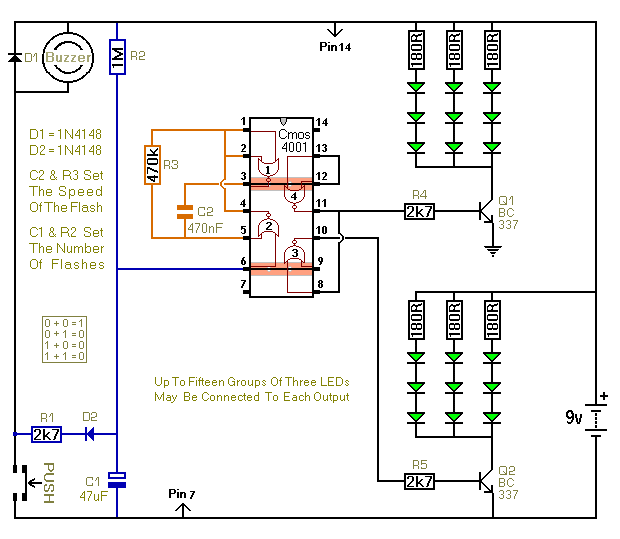
When the push switch is activated, the buzzer sounds, and the LEDs start to flash. For the hearing members of the household, the buzzer functions as a standard doorbell, providing reassurance to the visitor that the doorbell is operational....

Before any accusations arise regarding the creation of a device designed to harm animals, it is essential to clarify that this device does not kill or harm dogs or any living creature. The issue began in a neighborhood where...
Although it does not have the same charm as real mercury barometers with long glass tubes on pieces of carved and polished wood, the Torricelli barometer. The Torricelli barometer, named after the Italian scientist Evangelista Torricelli, is an instrument used...