
how to build fridge door alarm

The circuit design comprises several key components, including the 4060 CMOS IC (or its substitute), resistors, capacitors, a diode, a photoresistor, and a piezo sounder. The photoresistor serves as a light sensor, detecting the illumination changes when the fridge door is opened. The capacitor C1 plays a crucial role in timing the delay before the alarm is triggered. The astable multivibrator configuration of both IC1 and IC2 allows for the generation of square wave signals, which are essential for driving the piezo sounder to produce the alarm sound.
In practical application, the circuit should be enclosed in a durable, insulated box to prevent moisture ingress and ensure reliable operation in a refrigerated environment. Proper placement within the fridge is critical; positioning near the light source maximizes the sensitivity of the photoresistor, ensuring prompt activation of the alarm when the door is opened. Furthermore, the choice of components should consider temperature variations and humidity levels typical of refrigerator environments to maintain consistent performance.
Overall, this design modification enhances the functionality of the Fridge Door Alarm circuit, extending its operational voltage range and improving reliability, thereby providing an effective solution for users seeking to monitor their fridge doors effectively.The main purpose of this design was to obviate a small defect of the very popular Fridge Door Alarm circuit, available on this website since 1999 and built by a lot of hobbyists. Unfortunately, that circuit stops operating when the battery voltage falls below about 2. 6 - 2. 7 Volts. This is due to the 4060 CMos IC used. In some cases, devices made by some manufacturers (but not Motorola`s) fail to operate even at nominal 3V supply voltage. A simple cure to this shortcoming could be the substitution of the original IC specified with a 74HC4060 chip: this should allow circuit operation down to 2V but, unfortunately, this IC is not easy to locate. For this reason, an equivalent circuit using about the same parts counting was developed, in order to allow safe operation even when battery voltage falls down to about 1.
3V. The circuit, enclosed in a small box, should be placed in the fridge near the lamp (if any) or close to the opening. With the door closed, the interior of the fridge is in dark, the photo resistor R2 presents a high resistance (>200K) thus clamping IC1 by holding C1 fully charged across R1 and D1.
When a beam of light enters from the opening, or the fridge lamp lights, the photo resistor lowers its resistance (<2K) stopping C1 charging current. Therefore IC1, wired as an astable multivibrator, starts oscillating at a very low frequency and after a period of about 24 sec.
its output pin (#3) goes high, enabling IC2. This chip is also wired as an astable multivibrator, driving the Piezo sounder intermittently at about 5 times per second. The alarm is activated for about 17 sec. then stopped for the same time period and the cycle repeats until the fridge door closes. 🔗 External reference
Related Circuits

The project presented involves a verified circuit diagram for a two-tone doorbell that produces a "ding-dong" sound. It is part of a collection of various doorbell and alarm projects. The two-tone doorbell circuit typically utilizes a combination of capacitors, resistors,...

An AC-triggered multitone, polyphonic doorbell that plays eight melodious tunes for a duration of two minutes. Each button press activates a new tone that continues until the melody concludes. The circuit is designed to be simple and operates on...

This circuit utilizes a CMOS 4017 decade counter, which begins counting from zero and increments by one each time pin 14 is activated. Upon reaching a count of nine, it resets to zero and starts the counting process again....
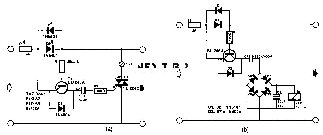
The circuit in Fig. 56-lla activates a signal lamp when it detects a line current consumption exceeding 5 mA and can handle currents of several amperes using suitable diodes in the D1 and D2 positions. Transistor T1 is activated...

In a panic situation during the night when an intruder attempts to break into a house, this alarm system will assist by emitting a loud police siren to deter the intruder. The alarm system is designed to enhance home security...

Personal Alarm Circuit Diagram. If you feel threatened or need urgent support in a crowd, use this alarm to catch the attention of others. The personal alarm circuit is designed to provide a loud audible signal when activated, serving as...