
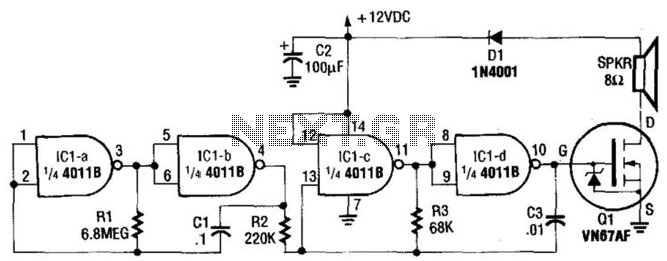
2 Tone Door Bell

The two-tone doorbell circuit typically utilizes a combination of capacitors, resistors, and a microcontroller or an integrated circuit (IC) to generate distinct sound patterns. The two tones are often produced by utilizing two different frequencies, which can be achieved through the use of a tone generator IC or a simple oscillator circuit that modulates the output sound.
In a standard implementation, the circuit may include a push-button switch that activates the doorbell when pressed. This switch is connected to the input of the tone generator. The output from the tone generator is then fed into a power amplifier circuit to drive a speaker or a piezo buzzer, which produces the audible sound.
Power supply considerations are crucial, as the circuit may require a DC voltage source, typically between 5V to 12V, depending on the components used. Proper filtering and decoupling capacitors should be included to ensure stable operation and to minimize noise in the output sound.
To enhance functionality, additional features such as adjustable volume control, different sound patterns, or even wireless capabilities can be integrated into the circuit design. This allows for customization and flexibility in different installation environments.
Overall, the two-tone doorbell circuit serves as an effective solution for alerting individuals to visitors while providing an aesthetically pleasing sound experience.2 Tone Door Bell here published is verified project produce ding-dong sound circuit diagram of 2-tone door bell with description.various door bell and alarm project . 🔗 External reference
Related Circuits
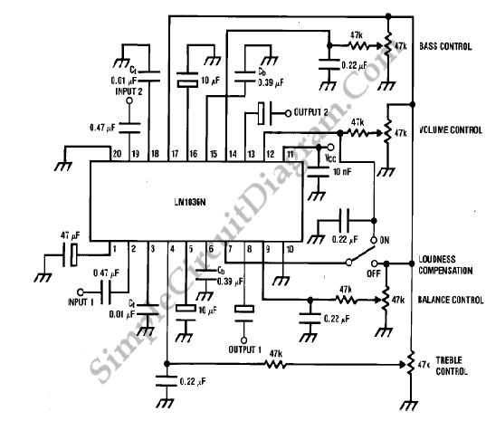
The LM1036 is a DC-controlled circuit designed for tone adjustment (bass/treble), volume control, and balance. It is suitable for use in car radios, televisions, and audio systems. The circuit also incorporates loudness compensation. The LM1036 integrates several functionalities essential for...
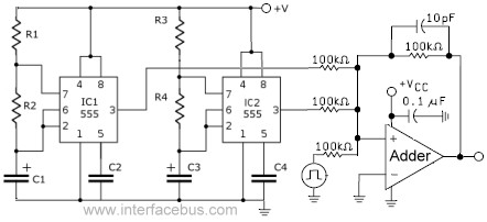
This circuit combines the outputs from two distinct 555 multivibrators using a summing operational amplifier (Op Amp). It serves to illustrate an alternative implementation of a 555 timer, with most background calculations addressed in other sections. The standard configuration...
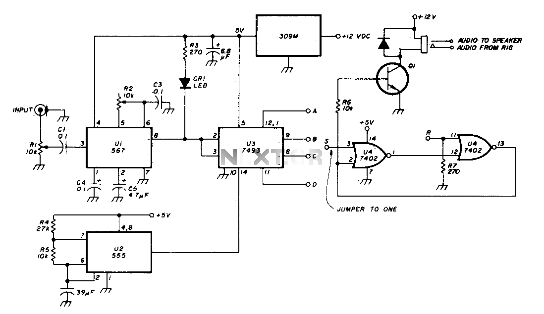
The Phase-Locked Loop (PLL) integrated circuit (U1) is configured with resistor R2 to achieve the desired tone frequency. An LED indicator is used to show when the PLL has locked onto the signal. To ensure proper lock-up, the signal...
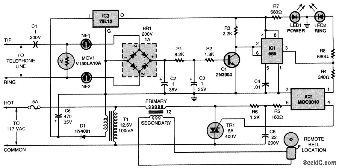
The telephone line extension bell ringer enables the addition of a remote ringer in locations such as a garage, where the sound of a ringing telephone may not be audible. Up to four ringers can be connected to a...
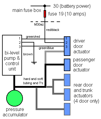
There are two systems of pneumatic central locking in vintage Audis. Earlier models are controlled by the driver's door lock, while later models use both front door locks. The earlier models (5000/100/200 before 1984, 4000/Coupe/Quattro/80/90 before 1988) utilize a...
This circuit utilizes a CMOS chip and a VMOS FET amplifier to achieve 6 W of audio output. With a +24 Vdc power supply, it can generate up to 18 W of audio. IC1A and IC1B function as a...