
How to build Modular Class A Buffer preamplifier
The described circuit functions as an isolation amplifier, suitable for applications where signal integrity is paramount, such as in audio processing. The use of local negative feedback allows for a controlled gain of X1, which helps maintain the fidelity of the audio signal while minimizing distortion. This characteristic is essential in high-fidelity audio applications where any introduction of noise or distortion can significantly degrade performance.
The careful selection and matching of transistors are critical to ensure optimal performance. Transistor parameters such as beta (current gain), Vbe (base-emitter voltage), and thermal characteristics must be closely aligned to ensure that the circuit operates effectively under varying conditions. Mismatched transistors can lead to imbalances that may introduce unwanted noise or distortion, thus it is recommended to use transistors from the same batch or series.
The inclusion of resistors between the transistors plays a vital role in setting the biasing conditions and stabilizing the operating point of the transistors. The values of these resistors should be calculated based on the desired operating current and voltage levels to ensure that the transistors operate within their linear region.
Thermal coupling is another important aspect of the design, as it ensures that the temperature variations in one transistor do not adversely affect the other. This is particularly critical in high-power applications where thermal runaway can occur. The thermal union between the transistors and the associated diodes (D1 and D2) allows for effective heat dissipation and ensures that the operating temperatures remain stable.
Diodes D1 and D2 serve as indicators or protection elements in the circuit, providing visual feedback on the operational status of the transistors Q5 and Q2. Proper orientation and connection of these diodes are essential to ensure that they function correctly within the circuit.
Overall, this circuit design emphasizes the importance of component selection, thermal management, and feedback mechanisms to achieve high performance and reliability in sound circuit applications.A unit which is often very useful, if we need to isolate, in sound circuits, two stage between them. Then we can use this circuit which has an amplified unit, which gain X1, we do not use total negative feedback, only local, with the result that distortion remains at a very low level. Matching must be done with great care to the types of transisto rs, resistor between them. There must also be thermal union between the transistors, as well as the diodes LED D1-2 with the transistor Q5 and Q2 respectively. 🔗 External reference
Related Circuits
The IR Beam Breaker Circuit Diagram is designed as an infrared beam breaking alarm suitable for use in entryways or passageways. This circuit utilizes the well-known IR sensor module TSOP 1738, which detects 38 kHz infrared pulses emitted by...
A Class A Class AB amplifier rated 100 Watts when driving a 4 ohm loudspeaker. This circuit developed out of my 30+ years of JLH class-A based investigations. The original simple 1969 JLH class-A design provided excellent first cycle accuracy...
This preamplifier is designed to interface with CD players, tuners, tape recorders, and similar devices, providing an AC voltage gain of 4 to drive less sensitive power amplifiers. Given that modern Hi-Fi home equipment often comes with small loudspeaker...
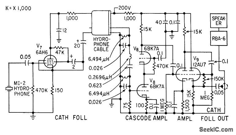
A cathode-follower hydrophone isolation amplifier and high-gain preamplifier are used to feed the Navy RBA-6 low-frequency radio receiver on a trawler. This setup is designed to receive a modulated 21-kc beam that transmits data regarding trawl net depth. The...

An expanded scale voltmeter (ESV) can be crucial for aircraft operation. This assertion is based on the dependency of the radio link, which allows control of the aircraft, on nickel-cadmium (NiCd) batteries located in both the transmitter and receiver....
When designed with general-purpose small-signal transistors, the bandwidth ranges from 50 MHz to 250 MHz, necessitating careful grounding and power supply decoupling. The simulation schematic illustrates a two-transistor buffer. Due to copyright issues, models from other sources are not...