
Stereo preamplifier with bass circuit
The described preamplifier circuit is engineered to enhance audio signals from various sources, ensuring compatibility with equipment that may have lower sensitivity. The primary function of the preamplifier is to amplify the incoming audio signal by a factor of four, which is particularly beneficial when interfacing with power amplifiers that require a stronger input signal for optimal performance.
To further enhance the listening experience, the circuit incorporates a bass-boost feature, which is crucial for compensating for the inherent limitations of small loudspeaker cabinets that may not reproduce low-frequency sounds effectively. The bass-boost circuit allows for tailored adjustments to the low-frequency response, providing flexibility to the user. By utilizing a variable resistor, the user can fine-tune the bass boost from 0 dB, where no additional boost is applied, to a maximum of +16 dB at a frequency of 30 Hz. This adjustment capability ensures that the audio output can be optimized according to personal preferences or specific acoustic conditions.
For applications where a consistent bass boost is desired without the need for user adjustments, the variable resistor can be bypassed by incorporating a switch. This configuration allows for a fixed maximum boost level to be set, simplifying the operation for users who prefer a straightforward setup.
In terms of implementation, the circuit typically includes standard components such as resistors, capacitors, and operational amplifiers configured to achieve the desired gain and frequency response characteristics. Proper power supply decoupling and grounding techniques should be employed to minimize noise and ensure high fidelity in audio reproduction. Overall, this preamplifier circuit is a versatile solution for enhancing audio signals in various home audio applications.This preamplifier was designed to cope with CD players, tuners, tape recorders etc. , providing an ac voltage gain of 4, in order to drive less sensitive power amplifiers. As modern Hi-Fi home equipment is frequently fitted with small loudspeaker cabinets, the bass frequency range is rather sacrificed. This circuit features also a bass-boost, in or der to overcome this problem. You can use a variable resistor to set the bass-boost from 0 to a maximum of +16dB @ 30Hz. If a fixed, maximum boost value is needed, the variable resistor can be omitted and substituted by a switch. 🔗 External reference
Related Circuits
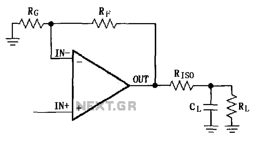
The MAX4223 to MAX4228 series incorporates a capacitive load drive circuit with an isolation resistor (RISO). The maximum allowable capacitive load for these devices is 25pF. However, exceeding this limit can lead to overshoot and ringing. The circuit design...
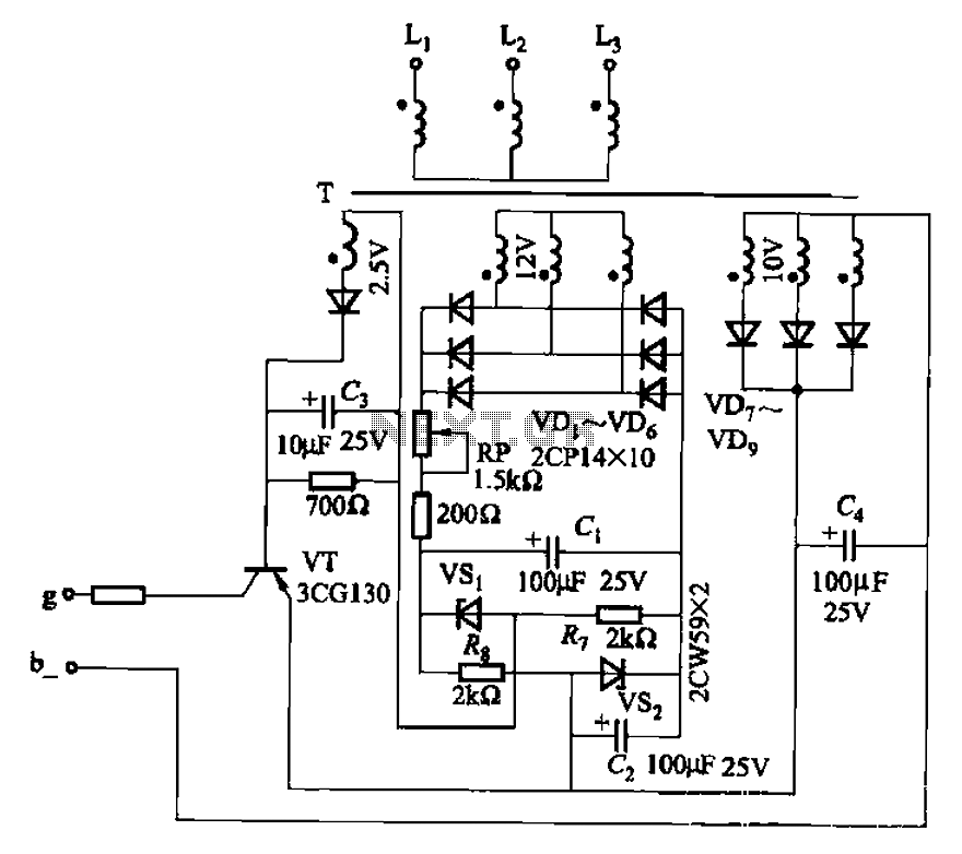
The CJ-12 Excitation Regulator is designed for automatic excitation control of small generators with a capacity of 250 kW or less. Its circuit is illustrated in Figure 7-45. The adjustment potentiometer RP allows for the modification of the measuring...
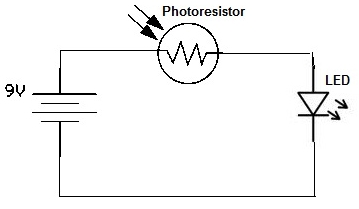
A simple photoresistor circuit will be constructed to demonstrate the operation of a photoresistor, which activates the circuit in the presence of light and deactivates it in darkness. This circuit connects a photoresistor to an LED. When the photoresistor...
Using an old moving coil instrument, it is easy to create a simple voltmeter that indicates the status of a telephone line at a glance. The circuit's high input impedance allows it to be permanently connected to the line,...
An FM transmitter circuit that utilizes a low power configuration, employing an operational amplifier as an audio preamplifier and a single transistor to function as the RF amplifier. This FM transmitter circuit is designed for low power applications, making...
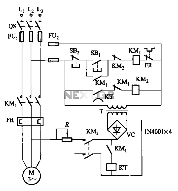
The circuit depicted in Figure 3-134 utilizes an automatic control braking mechanism, which is an enhancement based on the time relay system shown in Figure 3-133 (a). The KT control allows for an adjustable braking time of 2 to...