
Hydrophone preamplifier circuit

The hydrophone preamplifier circuit is designed to amplify the signals received from a piezoelectric transducer, which is commonly used in underwater applications for detecting sound waves. The piezo transducer converts acoustic energy into electrical signals, but due to its high output impedance, it requires a preamplifier that can effectively interface with it without significantly loading the transducer.
The circuit typically includes a high-impedance input stage, often implemented using a field-effect transistor (FET) or an operational amplifier configured in a voltage follower arrangement. This configuration ensures that the input impedance is sufficiently high to prevent signal attenuation from the transducer. The output stage of the preamplifier may include additional amplification stages to boost the signal level for further processing or transmission.
Key components of the circuit include resistors and capacitors that are selected to optimize the bandwidth and frequency response of the amplifier. Bypass capacitors may be employed to filter out any unwanted noise and ensure stable operation. The overall design is aimed at achieving low noise and high fidelity in the amplified signal, making it suitable for sensitive underwater acoustic measurements.
In summary, the hydrophone preamplifier circuit is a critical component in underwater acoustic systems, enabling effective signal amplification while maintaining the integrity of the original acoustic signals detected by the piezoelectric transducer.Hydrophone preamplifier circuit. As you can see, it`s really simple and uses only conventional components. The transducer used, is piezo type and has a relatively high output impedance, which requires a preamp with a high input impedance. 🔗 External reference
Related Circuits
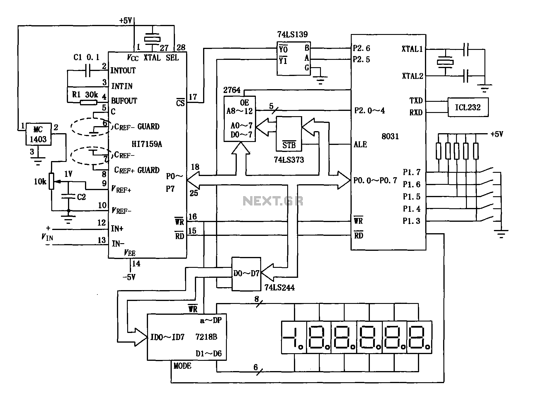
An intelligent digital voltmeter circuit utilizing the HI7159A, 8031 microcontroller, and various other components as illustrated in the figure. The internal circuit incorporates a successive cumulative integrator, digital zero function, low noise BIMOS technology, and other advanced features. In...
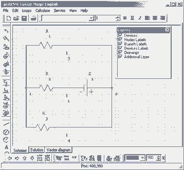
Circuit Magic is an electrical circuits simulation program specifically designed for students teaching basics electronics, electrical laws & circuit theory. Unlike many electronic circuit analyzers, Circuit Magic can analyze circuits like a man. Circuits are simulated step by step,...
The code implementation discussed in the previous post has been initiated. To improve organization, the code has been modularized into functions, simplifying the overall structure. It is available along with the other code. Challenges were encountered in calculating averages...
This circuit consists of five transistor time relay circuits designed for time relay exchange. It utilizes two different power supplies, maintaining the same circuit configuration. The delay time can be adjusted by modifying a potentiometer. The parameters for the...
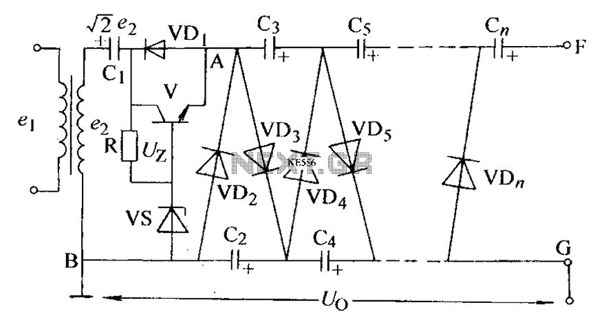
The circuit is an adjustable output voltage regulator type rectifier. It allows for obtaining peak voltage at odd multiples when the output voltage is taken from the circuit feedback (FB). Additionally, the lower point of the capacitor (CB) can...
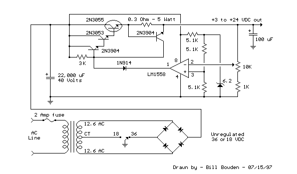
This regulated power supply can be adjusted from 3 to 25 volts and is current limited to 2 amps as shown, but may be increased to 3 amps or more by selecting a smaller current sense resistor (0.3 ohm)....