
Transistor time relay circuit

The five-transistor time relay circuit operates by leveraging the switching capabilities of transistors to control the timing functions. Each transistor is configured in a manner that allows for a series of time delays to be achieved through the manipulation of a potentiometer, which alters the resistance in the timing circuit. This adjustment directly influences the charge and discharge rates of any capacitors present, thereby affecting the overall delay time.
The circuit requires two distinct power supplies, which may be necessary to accommodate the different voltage levels required by the transistors and the relay. This dual power supply configuration enables flexibility in the design and can enhance the reliability of the circuit under varying conditions.
The time delay element, typically a transistor relay, is characterized by its parameters as outlined in Table 12-1. These parameters provide critical information regarding the operational limits and performance characteristics of the relay, including the maximum switching capacity and the response time.
The specified delay errors indicate the precision of the timing functions. A delay error of 1 to 50 seconds with a tolerance of 3% suggests that the circuit can be reliably tuned for short delays with minimal deviation. For longer delays, the 2 to 5-minute range with a tolerance of 6% indicates that while the timing can be extended, it may introduce a greater margin of error.
In practical applications, this circuit can be utilized in automation systems where precise timing is essential, such as in industrial machinery, lighting controls, or any system requiring timed operations. The ability to adjust the timing through a potentiometer adds versatility, allowing for easy recalibration based on specific operational needs.Five of the transistor time relay circuit b (a) for the exchange of time relay, Figure (b) is a linear flow of time following, the use of only two different power supply, the circuit is the same. Adjust the potentiometer can change the delay time. Time delay element JsJ transistor relay parameters listed in Table 12-1. Delay error: 1-50s when the soil 3%; 2-5min when 6%.
Related Circuits
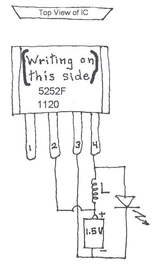
Many Joule Thief circuits traditionally rely on a bulky toroidal inductor that requires careful winding with copper wire. However, there are now compact 4-legged integrated circuits (ICs) available that can perform the same function using only a simple inductor,...
The current loop interface circuit diagram of the AD694 multi-functional sensor signal conditioner is utilized as a digital-to-analog converter (DAC). This current loop interface enables the conversion of digital values into voltage and subsequently into current signals. The circuit...
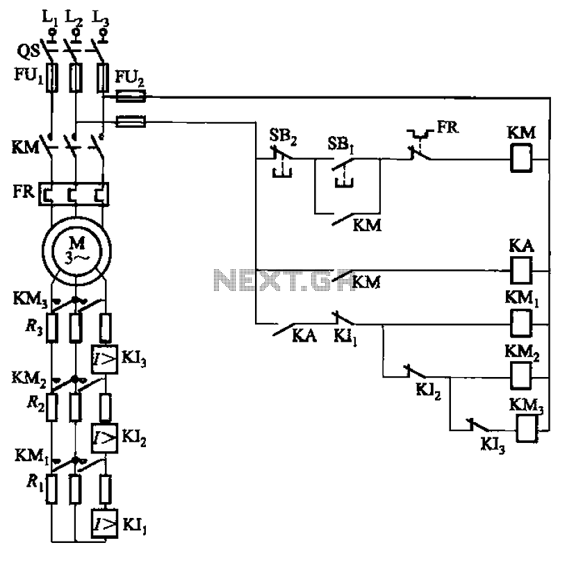
The circuit illustrated in Figure 3-161 features a first stage current detection mechanism utilizing a current relay (KI1) in series with a resistor (R1). The second stage employs another current relay (KI2) in series with a resistor (R2) for...
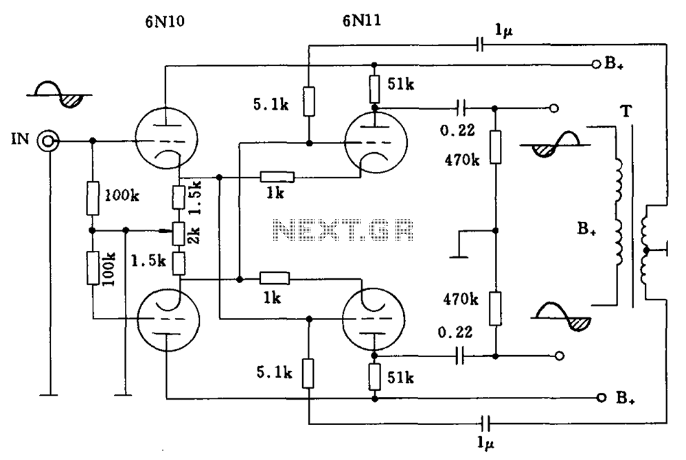
Balanced cross tube inverter circuit, also known as the Chelles inverter circuit, can be utilized as a preamplifier and employs 6N10 and 611 tubes in an inverted configuration. The circuit is designed to work with a final amplifier tube, specifically...
This is a VU meter circuit featuring 10 LEDs. This simple LED VU meter consists of only a few components, yet it serves as an effective indicator for sound levels. The circuit is constructed around an unspecified component. The VU...
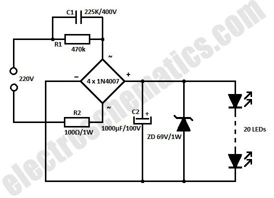
This white LED floodlight illuminates your porch with cool white light. The circuit features a simple and energy-saving design, with a low current consumption. The LED floodlight circuit typically consists of a power supply, a control circuit, and the LED...