
i2c rtc interfacing with lpc2129 arm7 tyro
The I2C bus operates effectively for communication between various devices, allowing for a structured and efficient exchange of data. The DS1307 RTC is particularly advantageous in applications requiring accurate timekeeping and calendar functions. The integration of the DS1307 with the LPC2129 Tyro Board highlights the versatility of I2C in embedded systems, enabling seamless communication and control. The design ensures that the master device can easily manage the slave device, facilitating real-time clock operations with minimal overhead. The use of Hyper Terminal for monitoring and controlling the RTC adds an interactive element, allowing for real-time adjustments and feedback during development and debugging phases. This setup is ideal for projects that necessitate precise timekeeping and can be expanded to include additional I2C devices as needed, enhancing the overall functionality of the system. The simplicity of wiring and the robust nature of the I2C protocol make it a suitable choice for a wide range of applications in electronics and embedded system design.The I2C (Inter-IC) bus is a bi-directional two-wire serial bus that provides a communication link between integrated circuits (ICs). I2C is a synchronous protocol that allows a master device to initiate communication with a slave device.
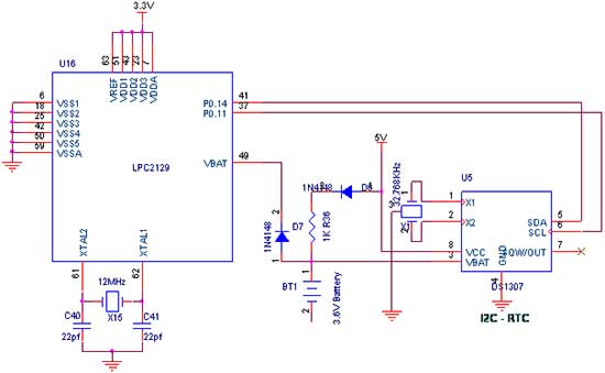
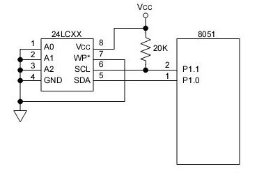
Data is exchanged between these devices. The DS1307 Serial Real-Time Clock is a low-power; full binary-coded decimal (BCD) clock/calendar plus 56 bytes of NV SRAM. Address and data are transferred serially via a 2-wire, bi-directional bus. The clock/calendar provides seconds, minutes, hours, day, date, month, and year information. The end of the month date is automatically adjusted for months with fewer than 31 days, including corrections for leap year. The clock operates in either the 24-hour or 12-hour format with AM/PM indicator. Fig. 1 shows how to interface the EEPROM with microcontroller through I2C. I2C is a Master-Slave protocol. I2C has a clock pulse along with the data. The master device controls the clock line, SCL. This line dictates the timing of all transfers on the I2C bus. No data will be transferred unless the clock is manipulated. I2c bus supports many devices, each device is recognized by a unique address ”whether it`s a micro-controller, LCD Driver, memory or keyboard interface and can operate as transmitter or receiver based on the functioning of the device.
The controller designed controls the RTC ds1307 device through I2C protocol. The I2C Controller here acts as a master device and controls RTC ds1307 which acts as a slave. The read operation is accomplished by sending a set of control signals including the address and/or data bits. The control signals must be accompanied with proper clock signals. We now want to read date & time by using I2C - RTC in LPC2129 Tyro Board. Wiring up an I2C based RTC to the I2C port is relatively simple. The RTC also makes the software easier as it takes care of all calendar functions; accounting for leap years etc.
The DS1307 (RTC) Real Time Clock IC (an I2C real time clock) is an 8 pin device using an I2C interface. In LPC2129 TYRO Kit, 2 nos. of RTC lines are controlled by I2C Enabled drivers. I2C Lines serial clock SCL (P0. 2), serial data SDA (P0. 3) connected to the I2C based serial RTC ds1307 IC. The date & times are read in LPC2129 Tyro Kit by using these SDA & SCL I2C lines. To compile the above C code you need the KEIL software. They must be properly set up and a project with correct settings must be created in order to compile the code.
To compile the above code, the C file must be added to the project. In Keil, you want to develop or debug the project without any hardware setup. You must compile the code for generating HEX file. In debugging Mode, you want to check the port output without LPC2129 Tyro Board. Give +3. 3V power supply to LPC2129 Tyro Board; the RTC Battery device is connected with the Tyro Board. First check the entire Battery device fixed properly. A serial cable is connected between the microcontroller and PC. In PC, open the Hyper Terminal for displaying the values from RTC. Now, the Hyper Terminal shows the received data from RTC Battery through I2C. If you want to change the time value from RTC Battery then you just Turn ON the switch, sw3. Now, you can write any new time values into the RTC by using Hyper Terminal. Then Turn OFF switch, sw3. Now the RTC Battery start the new time value & it display in Hyper Terminal. The Hyper Terminal is working b 🔗 External reference
Related Circuits
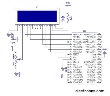
The RW line is the "Read/Write" control line. When RW is low (0), the information on the data bus is being written to the LCD. When RW is high (1), the program is effectively querying (or reading) the LCD....
This EEPROM programmer is designed to read, write, and erase 24C EEPROM devices. It features a PC serial port interface and requires a 5V DC power supply. The programmer can read or write one page (16 bytes) at a...
The PS-LPC2138 ADK, an ARM Development Kit, is designed to facilitate the development and debugging of various designs using a high-speed 32-bit microcontroller (MCU) from NXP. This board is compatible with the LPC214x family of devices and offers multiple...
The i2c-tiny-usb project is an open source/open hardware project. The goal of i2c-tiny-usb is to provide a cheap generic i2c interface to be attached to the usb. It is meant as a replacement for those simple and cheap printer...
A keyboard is a fundamental component of an embedded or microcontroller system. For small-scale and hobby projects, a 4x4 (hex) matrix keyboard is adequate. The keys in the matrix keyboard are arranged in a matrix configuration to efficiently utilize...
This article outlines a reliable, straightforward, and universal method for interfacing Motorola mobile radios from the MaxTrac, Radius, and GM300 series with common repeater controllers. The information provided is also relevant for radio interfaces used in IRLP or EchoLink...