
16x2 Alphanumeric LCD Interfacing :: AVR Tutorials
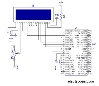
The example program for 4-bit LCD interfacing with ATmega16 is defined in the file named LCD.h, which is to be included in the main program. The compiler used is WinAVR / AVR GCC. The LCD is connected to PORTB. The relevant control pins are defined as follows: LCD_RS is pin 0G—01, LCD_RW is pin 0G—02, and LCD_EN is pin 0G—08.
The function lcd_reset initializes the LCD by setting the port to high, introducing delays, and toggling the enable pin to reset the LCD state. The function lcd_cmd sends commands to the LCD by first sending the upper 4 bits followed by the lower 4 bits, with appropriate delays in between. The lcd_init function calls lcd_reset and sends a series of commands to set the LCD to 4-bit mode, configure it for two lines, set the font size, and adjust the display settings.
The function lcd_data is used to display a single character on the LCD. It sends the upper and lower 4 bits of the data byte while setting the RS pin to indicate that data is being sent. The main program, defined in main.c, initializes the LCD, clears the screen, and writes a string to the first line and another string to the second line, entering an infinite loop thereafter.
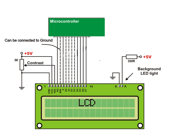
In this context, the RW line plays a crucial role in determining the operation mode of the LCD. The low state indicates writing data to the display, while the high state is reserved for querying the status of the LCD, which is a rare operation in typical usage scenarios. The 4-bit mode of operation is particularly advantageous as it reduces the number of required GPIO pins, allowing for more efficient use of microcontroller resources.
The example program demonstrates how to interface the LCD with an ATmega16 microcontroller, outlining the necessary functions to initialize the display, send commands, and display data. The use of delays is essential to ensure proper timing in communication with the LCD. This approach showcases an effective method for integrating an LCD display into embedded systems, providing a simple yet functional interface for user interaction.The RW line is the "Read/Write" control line. When RW is low (0), the information on the data bus is being written to the LCD. When RW is high (1), the program is effectively querying (or reading) the LCD. Only one instruction ("Get LCD status") is a read command. All others are written commands so RW will almost always be low. >>While using LCD in 4 bit data mode it saves 4 bits of our total GPIO lines, that ’s why it is most commonly used. MSB of any data or commnad is sent first over 4 bits and then 4 LSB sent by shifting the data byte 4 times left. /* Example program For 4 bit LCD interfacing with ATmega16 File name - LCD. h (to be included in main program) Compiler - WinAVR / AVR GCC <7465> / #define lcd_port PORTB //LCD connected to PORTB as shown above #define LCD_RS 0G—01 #define LCD_RW 0G—02 #define LCD_EN 0G—08 void lcd_reset(void) { lcd_port = 0xFF; _delay_ms(20); lcd_port = 0G—30+LCD_EN; lcd_port = 0G—30; _delay_ms(10); lcd_port = 0G—30+LCD_EN; lcd_port = 0G—30; _delay_ms(1); lcd_port = 0G—30+LCD_EN; lcd_port = 0G—30; _delay_ms(1); lcd_port = 0G—20+LCD_EN; lcd_port = 0G—20; _delay_ms(1); } void lcd_cmd (char cmd) { lcd_port = (cmd & 0xF0)|LCD_EN; lcd_port = (cmd & 0xF0); lcd_port = (cmd << 4) & 0xF0)|LCD_EN; lcd_port = (cmd << 4) & 0xF0); _delay_ms(2); _delay_ms(2); } void lcd_init (void) { lcd_reset(); // Call LCD reset lcd_cmd(0G—28); // 4-bit mode – 2 line – 5G—7 font.
lcd_cmd(0G—0C); // Display no cursor – no blink. lcd_cmd(0G—06); // Automatic Increment – No Display shift. lcd_cmd(0G—80); // Address DDRAM with 0 offset 80h. } // Function to display single Character void lcd_data (unsigned char dat) { lcd_port = (dat & 0xF0)|LCD_EN|LCD_RS); lcd_port = (dat & 0xF0)|LCD_RS); lcd_port = (dat << 4) & 0xF0)|LCD_EN|LCD_RS); lcd_port = (dat << 4) & 0xF0)|LCD_RS); _delay_ms(2); _delay_ms(2); } /* File name - main. c (demo program for 4 bit mode LCD interfacing) Compiler - WinAVR / AVR GCC */ #include
com"); lcd_cmd(0xc0); // Command to goto second line lcd_puts("LCD 4 Bit"); while(1=1); // loop forever return 0; } 🔗 External reference
Related Circuits
The circuit described is recommended for SSTV applications utilizing a sound card connected to a computer. It follows the JVComm style of interface and can also be employed for RTTY and PSK31 applications. Many users modify this circuit to...
This article discusses the Gadgets, Gizmos, and Arduino (ATMega328). The content is straightforward and informative. The components mentioned in this article can enhance the understanding of the subject. For instance, readers can find and purchase components such as the...
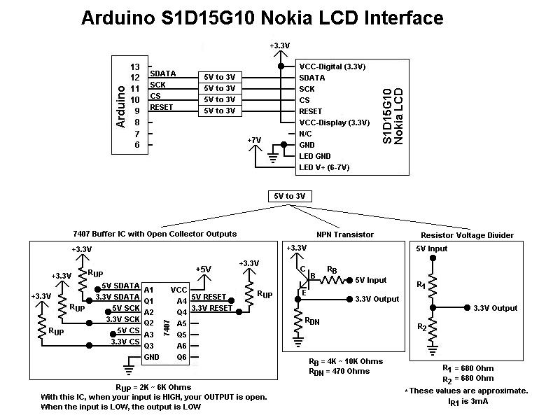
This is the first color graphic LCD display encountered. Initial assumptions were made regarding the connections, specifically that the Chip Select (CS) and RESET pins could be tied high for simplicity, based on previous experience with TTL logic. However,...
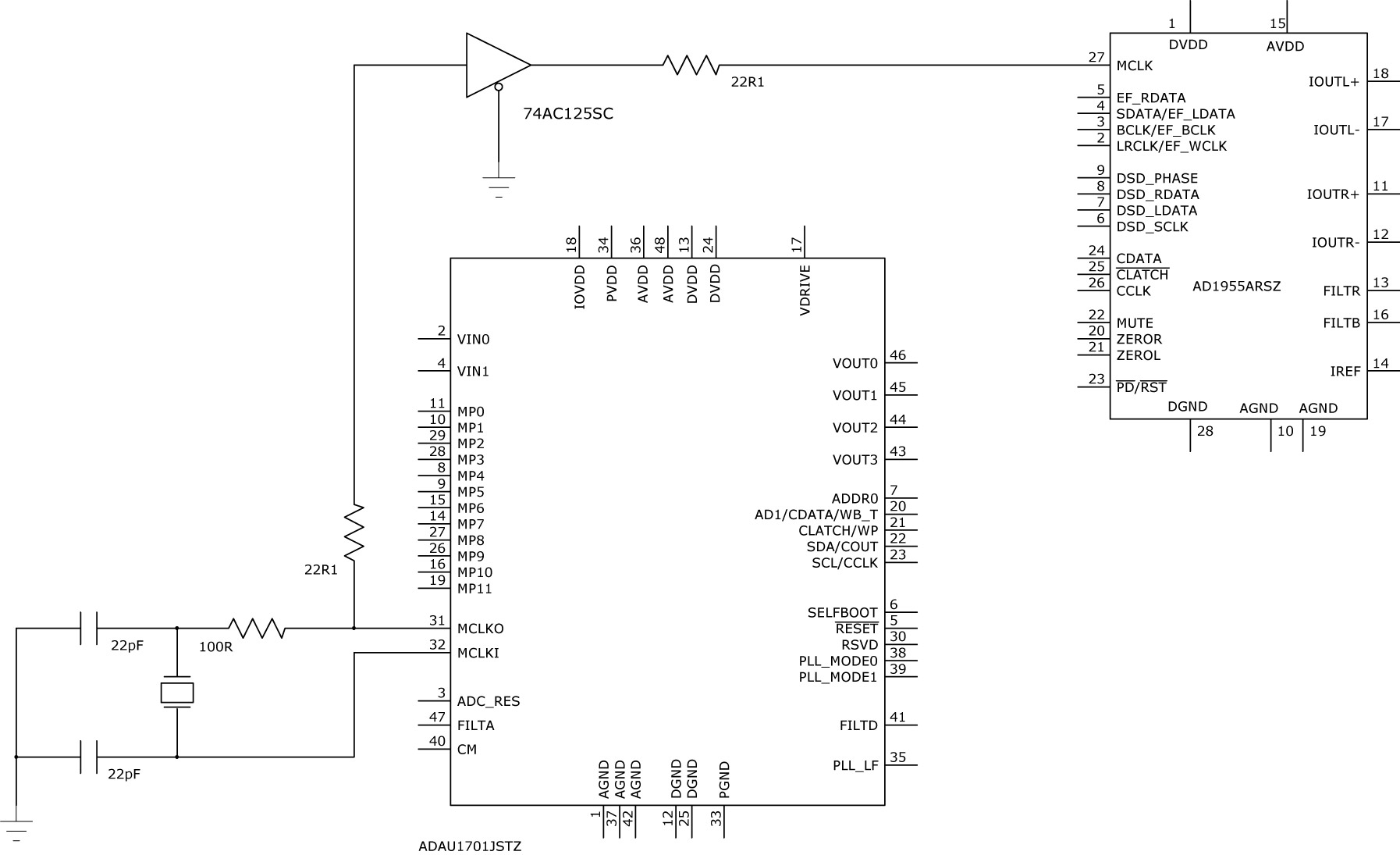
The ADAU1701 datasheet recommends on page 18 that MP11 should be used to derive MCLK. Additionally, MP11 also serves the purpose of OUTPUT_BCLK when used for I2S. This raises the question of whether MCLK and BCLK can be connected...
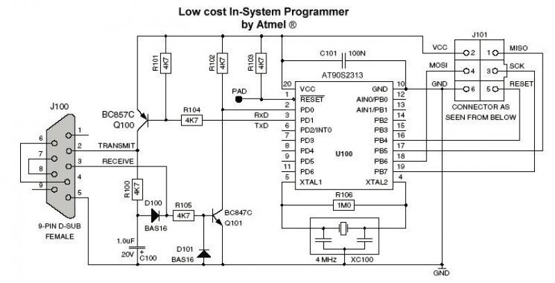
The ATMEL AVR family has established a strong presence in the microcontroller market. These microcontrollers offer a fast core and a variety of peripherals, which continue to attract the attention of engineers and gain their preference. Developers will find...
Learn how to interface a 16x2 LCD with the 8051 microcontroller. Download free source code for LCD interfacing with the 8051 microcontroller. The interfacing of a 16x2 Liquid Crystal Display (LCD) with the 8051 microcontroller is a common practice in...