
Ignition Coil Buzz Box circuit
The buzz coil circuit utilizes a standard automotive ignition coil, which is designed to transform low voltage from the vehicle's battery into a high-voltage spark necessary for igniting fuel in an engine. The core component of this circuit is the 556 dual timer, which consists of two independent timers that can be configured in various modes, including astable and monostable operations.
In this application, one of the timers is configured in astable mode to generate a continuous 200 Hz rectangular waveform. This waveform serves as the control signal for the gate of the IRF740 MOSFET, a power MOSFET capable of handling high voltages and currents. The IRF740 acts as a switch, allowing the current from the ignition coil to be rapidly turned on and off in synchronization with the generated waveform.
The second timer is configured to operate in monostable mode, where it responds to the state changes of the breaker points. When the breaker points close, the timer triggers the oscillator, allowing the MOSFET to conduct and energize the ignition coil. Conversely, when the breaker points open, the timer deactivates the oscillator, cutting off the current flow to the coil. This switching action results in the production of a series of high-voltage sparks emitted from the ignition coil, with a consistent interval of approximately 5 milliseconds between each spark while the breaker points remain closed.
The design of this circuit is particularly effective for applications requiring a high-frequency spark generation, such as in ignition systems or for creating a buzz coil effect in various electronic projects. Proper attention should be paid to the component ratings, ensuring they can handle the voltages and currents involved, particularly the MOSFET and the ignition coil, to prevent damage during operation. Additionally, adequate heat dissipation measures should be implemented for the MOSFET to maintain reliable performance during extended use.Here`s a circuit to create a buzzcoil using a standard automotive ignition coil. A 556 dual timer is used to establish the frequency and duty cycle of the coil current. One of the timers is used as an oscillator to generate the 200 Hz rectangular waveform needed to control the (IRF740 MOSFET) while the second timer switches the oscillator on and off as the breaker points open and close (closed = on). The result is a steady stream of sparks from the ignition coil spaced about 5 milliseconds apart while the breaker points are closed..
🔗 External reference
Related Circuits
This is a simple 50 MHz auto-ranging frequency meter developed as a course project by Simone Benvenuti and Andrea Geniola. It utilizes a single PIC 16C84 microcontroller and four displays to measure frequencies in the range of 0 Hz...
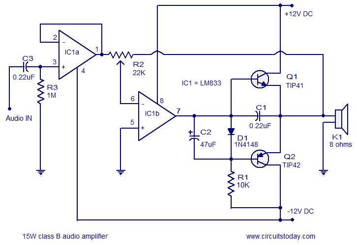
A 15 Watts Class B audio amplifier circuit is designed using a dual op-amp LM833. The schematic diagram is provided, and a potentiometer allows for volume control. The 15 Watts Class B audio amplifier circuit utilizes the LM833 dual operational...
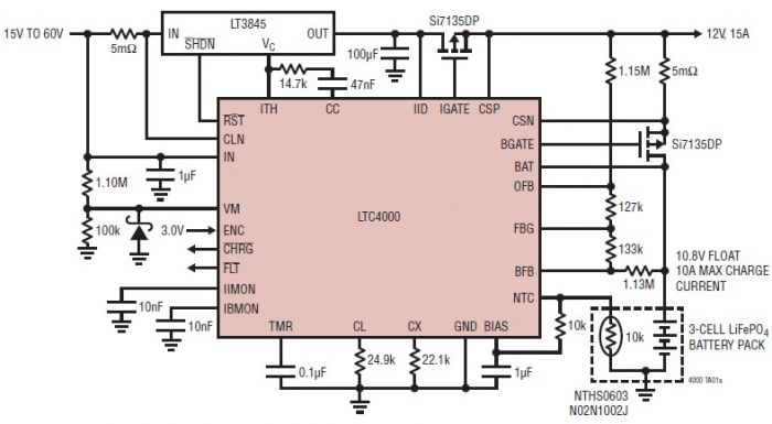
The LTC4000 high voltage controller, developed by Linear Technology, can be utilized to create a straightforward high current LiFePO4 battery charger. This charger delivers a fixed output voltage of 12 volts with a maximum output current of 15 A....
This ultra-bright white LED lamp operates on 230V AC with low power consumption. It is suitable for illuminating VU meters, SWR meters, and similar applications. The ultra-bright LEDs available in the market range from Rs 8 to 15. These...
A preamp circuit in a powered subwoofer is producing a static or popping noise, reminiscent of a scratchy or dirty sound. The preamp circuit in question is crucial for amplifying low-level audio signals before they are sent to the power...
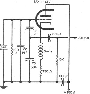
To update the fundamental oscillator circuits, simply replace the transistors with tubes. Alternatively, if one owns a vintage vacuum tube radio, it may be of interest to learn about historical practices. In general, the foundational principles of electronic circuits...