
Audio Amplifier Circuit 15 Watts Class B

The 15 Watts Class B audio amplifier circuit utilizes the LM833 dual operational amplifier to achieve high fidelity audio amplification. The LM833 is known for its low noise and distortion characteristics, making it suitable for audio applications. The circuit typically includes a power supply section, input stage, gain stage, and output stage.
In the input stage, the audio signal is fed into the non-inverting input of the first op-amp. This stage may also include coupling capacitors to block any DC offset from the audio source. The gain of this stage can be adjusted using resistors configured in a feedback loop.
The potentiometer connected to the circuit serves as a volume control, allowing the user to adjust the amplitude of the input signal before it is amplified. This component is typically placed in series with the input signal path, ensuring that changes in resistance directly affect the signal level entering the amplifier.
The output stage of the amplifier is designed to drive a load, such as a speaker. It typically employs complementary push-pull transistors to achieve Class B operation, where each transistor conducts for half of the input signal cycle. This configuration allows for efficient operation and minimizes power dissipation.
The schematic diagram illustrates the connections between the LM833, the potentiometer, and the output transistors, providing a clear visual representation of the circuit layout. Proper decoupling capacitors are also included in the design to filter out any high-frequency noise and ensure stable operation of the op-amps.
Overall, this 15 Watts Class B audio amplifier circuit is an effective solution for driving speakers in various audio applications, providing a balance between performance and efficiency.15 Watts Class B Audio amplifier circuit. This 15W amplifier circuit is designed using a dual op-amp LM833. Diagram and Schematics are shown. Potentiometer enables volume control.. 🔗 External reference
Related Circuits
A Butterworth filter is a type of filter characterized by a frequency response that is flat within the passband region. This filter was first described by British engineer Stephen Butterworth. A Butterworth filter is designed to provide a maximally flat...
A highly beneficial project involving a crystal tester circuit, also known as an xtal tester circuit, constructed with only a few components. The circuit forms an oscillator that will only oscillate if the crystal under test is functioning properly....
The receiver provides two TV signals, one for the living room and another for the bedroom, along with a satellite receiver. Watching television in the bedroom is convenient in Taiwan; however, when watching television in the living room, it...
This sawtooth generator circuit utilizes a 741 operational amplifier (op-amp) and functions as a musical sound synthesizer. The sawtooth input signal is continuously modified through potentiometer P2 to create varying waveforms. The sawtooth generator circuit primarily employs the 741 op-amp...
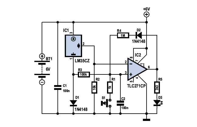
To determine whether it is freezing, one needs to measure the temperature accurately. This requires a reliable temperature sensor. The LM35CZ sensor, which operates within a range of -40 to 110 °C, is suitable for this purpose. It is...
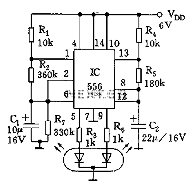
The circuit features a dual-core 556 timer IC and a light-emitting diode (LED) tube. The left half of the IC (556 1/2) comprises resistors R1, R2, capacitor C1, etc., generating a frequency of approximately 2 Hz in a multivibrator...