
INA155 156 input current protection circuit diagram

The INA155 and INA156 integrated circuits are designed to provide precision current sensing and signal conditioning, particularly in applications requiring robust input protection. The internal ESD protection diodes are essential for safeguarding the device against voltage transients that may occur due to external influences. When the input voltage rises beyond the threshold of 500mV above the supply voltage, the ESD diodes will clamp the excess voltage, ensuring that the internal circuitry remains safe from damage.
RLIM, a current limiting resistor, is strategically placed in the input path. Its primary function is to restrict the input current to a maximum of 10mA, which is crucial for preventing excessive current from flowing through the input stage of the INA155/156. This current limitation is vital for maintaining the integrity of the device's operation under various signal conditions. The design ensures that even in cases where the input signal itself may limit the current, RLIM is still present to provide additional protection.
In practical applications, it is important to consider the characteristics of both the input signal and the limiting resistor. The resistance value of RLIM should be chosen carefully to balance the need for current limiting with the desired signal integrity. The overall design of the input protection circuit ensures that the INA155/156 can operate reliably in environments where input signals may exceed expected voltage levels, thus enhancing the durability and performance of the electronic system. As shown in FIG grounds INA155/156 constituting the input current protection circuit. INA155 input internally with electrostatic discharge (ESD) protection diodes when the inpu t voltage exceeds the supply voltage 500mV, protection diodes will conduct case RLIM will limit the input current (maximum 10mA), play a role in the protection circuit. Many of the input signal itself limiting function, and this time the flow resistance RLIM can not.
Related Circuits
The basic circuit illuminates up to ten LEDs in sequence, following the rhythm of music or speech picked up by a small microphone. The expanded version can drive up to ten strips, formed by up to five LEDs each,...
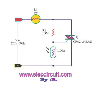
This is an automatic light dimmer circuit. There is no need to manually adjust the brightness of the lights. This circuit is highly convenient, as it utilizes a light-dependent resistor (LDR) to detect external light levels. The automatic light dimmer...
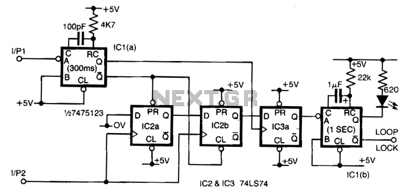
Input 1 functions as a gating period, during which a single rising edge on input 2 produces a logic 1 output. Any other input that indicates non-identical frequencies results in a logic 0 output. IC1a converts input 1 into...
This site addresses a range of subjects pertaining to circuits and electronics. Some of the topics discussed on this site include: * Alternating Relay Switch * Photoswitch Relay. The site serves as a comprehensive resource for understanding various electronic components...
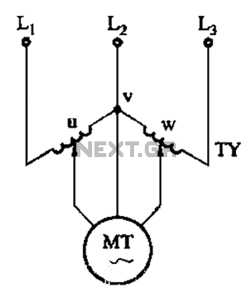
The circuit shown in Figure 3-177 utilizes two single-phase voltage regulators connected to a V-shaped configuration of single-phase regulators. This setup allows for the simultaneous adjustment of voltage and balance, enabling performance akin to a three-phase balanced adjustment. The circuit...
This circuit provides a simple visual indication of audio level signals, adaptable to various user requirements. It can be configured for different input levels, which can be adjusted using trimmer potentiometers TR1 (state) and TR2 (gain). The audio signals...