
12 led vu meter circuit

This audio level indicator circuit is designed to provide a clear, visual representation of audio signal levels, making it suitable for various applications in audio engineering and sound design. The circuit begins with an audio input, which is directed to the adjustable trimmers TR1 and TR2. TR1 is used to set the input signal state, while TR2 adjusts the gain of the incoming audio signal, allowing for optimal performance across different audio sources.
The rectification process is handled by diodes D1 and D2, which convert the alternating current (AC) audio signals into direct current (DC) signals. This rectification is crucial for ensuring that the subsequent stages of the circuit can accurately respond to the audio level changes. The output from the rectifiers is then fed into a series of diodes (D3 to D13) and transistors (Q2 to Q13) that serve as indicators of the audio level.
The transistors function as switches, activating the corresponding LED indicators (LD1-13) based on the rectified voltage levels. Each LED is designed to illuminate when the audio level exceeds a threshold of approximately 0.65 V, providing a clear visual feedback mechanism for users. The design allows for scalability; additional LEDs can be added to the circuit to increase the resolution of the audio level indication, as long as the power supply can support the added current requirements.
The total current requirement for the circuit is 100 mA, which should be considered when designing the power supply to ensure reliable operation. The use of standard components and the adaptability to various input levels make this circuit a versatile solution for audio signal monitoring in both professional and amateur audio setups.This is a simple visual indication of the audio level signals, adaptive to various user needs. Can be adapted to different input levels, adjustable by trimmer TR1 (state) - TR2 (Gain), then rectified by diodes D1-D2 (standard negative mark-recovery periods) and driven in the main circuit indication, consisting of the diodes D3 up to D13, transistors Q2-Q13 and materials that exist around them. The visual indicator is taken from the series of diodes LED LD1-13. Each Led illuminates when the level changed during about 0, 65 V. The power requirements are 100 ma full term. We can add as many steps we want LED, always assuming the power where you need the new LED. 🔗 External reference
Related Circuits

Construct a digital multimeter capable of measuring DC and AC voltages up to 100V and DC and AC currents up to 1A. The circuit will be powered by a 9V battery. The design incorporates a modified voltmeter to suit...
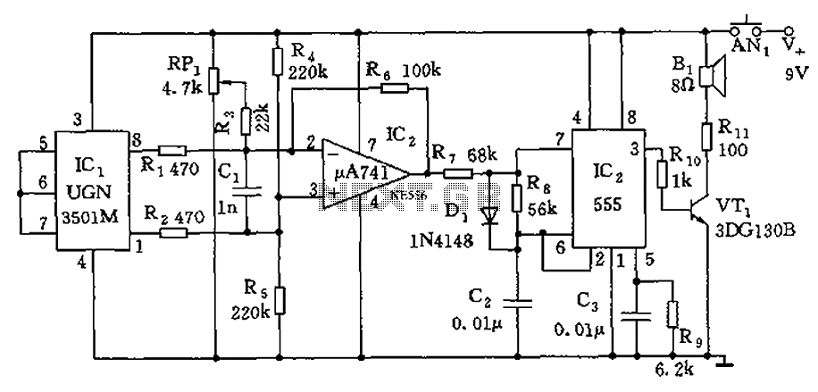
The circuit consists of a 555 timer and associated components designed for voltage-to-frequency conversion. It is utilized for determining the orientation of Earth's magnetic field using a Hall-effect sensor, specifically the UGN-3501M. This sensor incorporates a Hall element and...
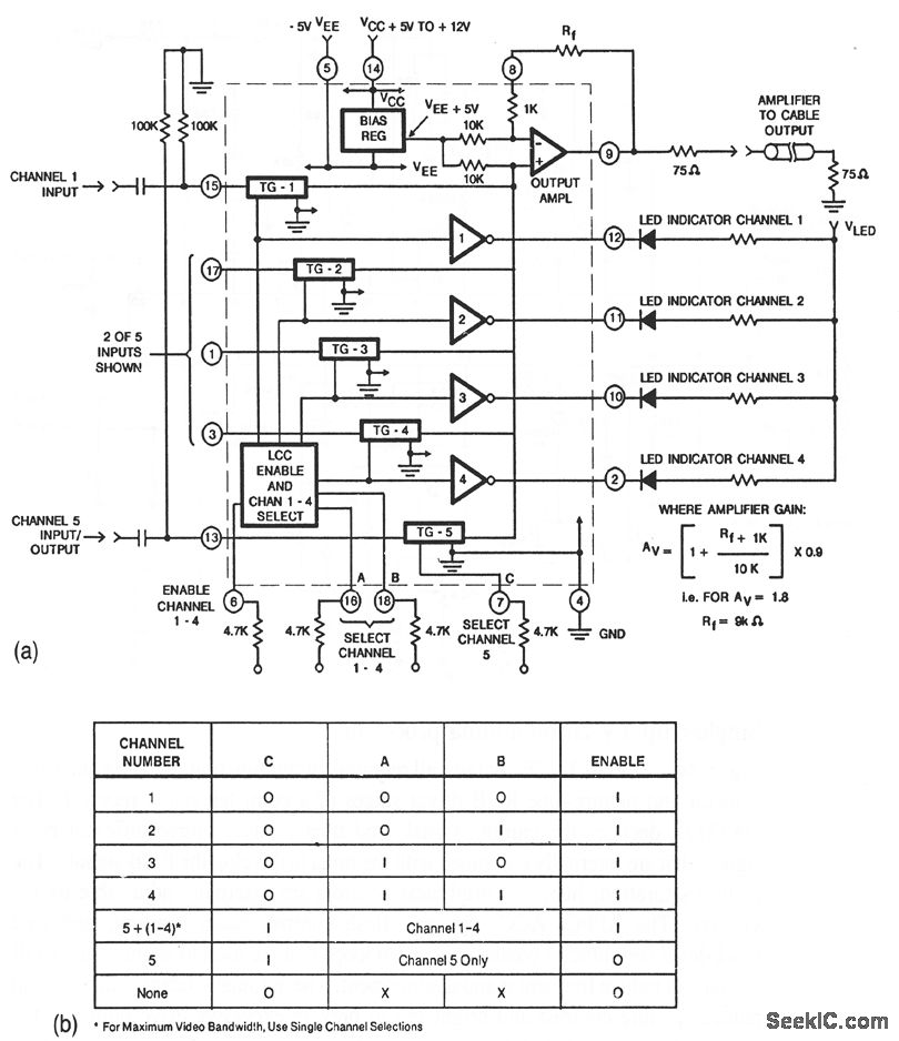
This circuit illustrates a CA3256 switch/amplifier configured for a direct-coupled output. One of four channels can be selected in parallel with channel 5. The analog switches of channels 1 to 4 are digitally controlled by logic. A VEE of...
This circuit is designed to provide a 4 LED bar graph that indicates the voltage of a common 3.6-volt Lithium-Ion rechargeable cell phone battery. The reference voltage is supplied by a TL431 programmable voltage source, which is configured to...
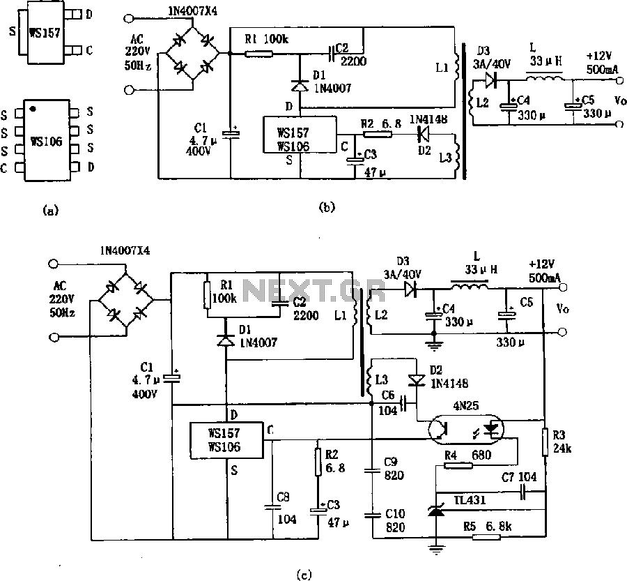
The WS157 or WS106 is a low-power miniature switching power supply that has been developed in recent years. It functions as a regulated switching power supply control device, featuring integrated internal control circuitry and power switches on a single...
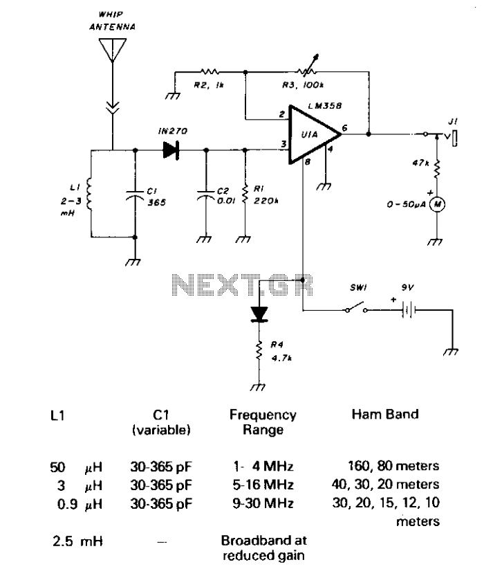
CI and LI resonate on the 1750-meter band, with coverage from 150 kHz to 500 kHz. LI can be slug-tuned for 160 to 190 kHz coverage alone, or a 2.5 mH choke can be used for LI, if desired,...