
Inductance Meter Adapter Circuit Turns Your Digital Voltmeter to Inductance Meter
An inductance meter adapter is a vital tool for accurately measuring the inductance of coils and inductors, which is essential for ensuring the desired performance in various electronic applications. This adapter typically interfaces with a digital multimeter or an oscilloscope to provide precise inductance readings.
The design of an inductance meter adapter generally includes a few key components: a microcontroller for processing measurements, a display for visual output, and various resistors and capacitors to create a stable measurement environment. The microcontroller can be programmed to calculate inductance based on the time constant of an RC (resistor-capacitor) circuit when the inductor is connected.
To use the adapter, the inductor is connected to the input terminals. The circuit applies a known voltage across the inductor and measures the resulting current. By analyzing the rise time of the current, the inductance can be calculated using the formula L = V / (di/dt), where L is the inductance, V is the applied voltage, and di/dt is the rate of change of current over time.
Additionally, the adapter may include features such as automatic range selection, calibration options, and the ability to store measurements for later reference. This enhances the usability and effectiveness of the tool for hobbyists and professionals alike, ensuring that inductors are built to specifications and function as intended in circuits.
In summary, an inductance meter adapter is an essential device for anyone involved in DIY electronics, providing the necessary means to accurately measure inductance and improve the quality of hand-made inductors.Measuring inductance is important in making your hand-made inductors, especially when you do-it-yourself (DIY) your coil winding. An inductance meter adapter.. 🔗 External reference
Related Circuits
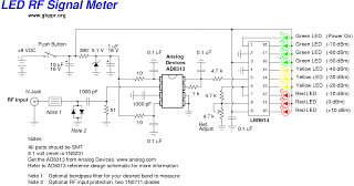
This device is a high-quality RF signal meter utilizing the Analog Devices AD8313 logarithmic detector integrated circuit (IC), which operates within the frequency range of 0.1 GHz to 2.5 GHz. It can detect signals as low as -80 dBm....
The ability amplifier has remained functional since it was first introduced in 2002. It is not broken, so there is no reason to fix it. The accompanying photo shows a well-assembled board (known as M27). Utilizing TIP35/36C transistors, the...
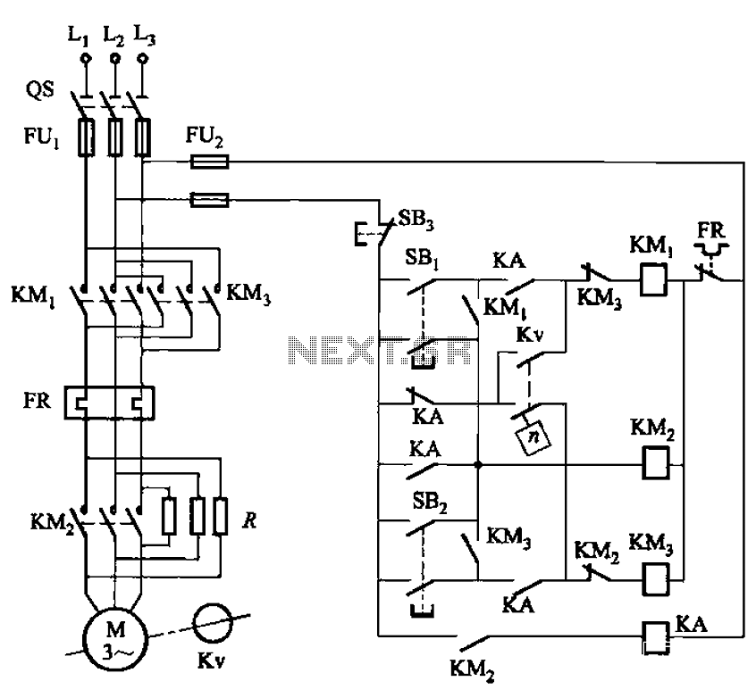
The circuit shown in Figure 3-129 is the C650-2 lathe brake control circuit, utilizing a speed control relay. The C650-2 lathe brake control circuit is designed to manage the braking mechanism of a lathe machine effectively. This circuit incorporates a...
The following circuit illustrates a Single Supply Phase Locked Loop Circuit Diagram. This circuit is based on the LM331 integrated circuit. Features include the response of... The Single Supply Phase Locked Loop (PLL) circuit utilizing the LM331 integrated circuit is...
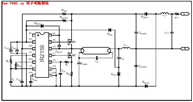
The IR2156 provides a cost-effective solution for fluorescent electronic ballasts. It integrates features such as lighting tube error protection and a programmable working frequency, which includes warm-up, lighting, and continuous operation of the ballast. The IR2156 is a highly integrated...
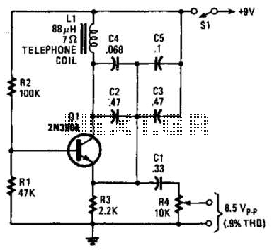
An 88 mH surplus telephone toroidal coil is utilized in a 1 kHz oscillator. It can provide up to 8 V peak-to-peak into a high-impedance load. The total harmonic distortion (THD) is 0.9%. The circuit employs an 88 mH toroidal...
Warning: include(partials/cookie-banner.php): Failed to open stream: Permission denied in /var/www/html/nextgr/view-circuit.php on line 713
Warning: include(): Failed opening 'partials/cookie-banner.php' for inclusion (include_path='.:/usr/share/php') in /var/www/html/nextgr/view-circuit.php on line 713