
LED RF Signal Meter
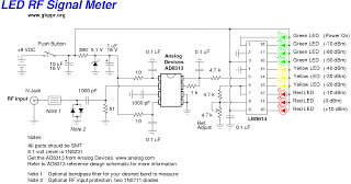
The RF signal meter designed around the AD8313 IC offers a robust solution for measuring radio frequency signals across a wide frequency range. The AD8313 features a logarithmic response that allows it to accurately measure low-level RF signals, making it suitable for various applications in telecommunications, electronics testing, and RF engineering.
The circuit design incorporates bandpass filters specifically tuned to the 2.4 GHz and 915 MHz ISM bands. These filters are essential for isolating the desired frequency signals while attenuating unwanted frequencies, thus enhancing the accuracy of the measurements taken by the AD8313. The output of the logarithmic detector provides a voltage level that correlates to the input signal strength, which can be easily visualized on a connected display or through an analog meter.
In terms of implementation, the RF signal meter's circuit may include additional components such as operational amplifiers for signal conditioning, voltage regulators to ensure stable operation, and connectors for interfacing with external measurement equipment. Proper grounding and shielding techniques are also critical in the design to minimize interference from external sources, which could affect the accuracy of the readings.
Overall, this RF signal meter is a valuable tool for professionals working in RF communications, enabling quick assessments of signal strength and noise levels in various environments. Its ability to detect low-level signals combined with the functionality of bandpass filters makes it an effective instrument for evaluating RF performance in the ISM bands.This is a high quality RF signal meter based around the Analog Devices AD8313 0. 1 GHz - 2. 5 GHz logarithmic detector IC. It is capable of detecting signals as low as -80 dBm. When combined with 2. 4 GHz or 915 MHz bandpass filters, it makes a quick visual reference to the amount of noise in the ISM bands in that particular location. 🔗 External reference
Related Circuits
Function: Used to measure the voltage change minute by management before the temperature diodes. Component: IC, Diode, Resistor, 3-1/2 digit LCD (SP521PR). The circuit described functions as a voltage measurement system designed to monitor minute voltage changes, particularly in relation...
This white LED floodlight illuminates your porch with cool white light. The circuit features a simple and energy-saving design, with a low current consumption. The LED floodlight circuit typically consists of a power supply, a control circuit, and the LED...
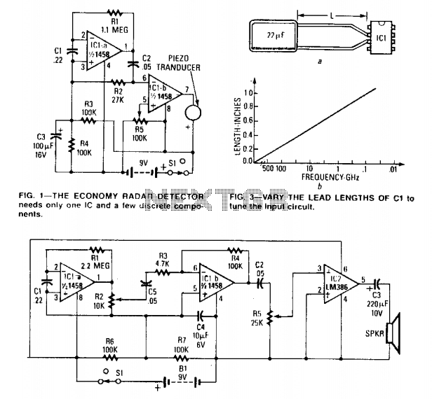
The circuit can be tuned to respond to signals between 50 MHz and 500 GHz. The economy model is illustrated in Figure 1, while the deluxe model is depicted in Figure 2. The first operational amplifier (op-amp) in each...
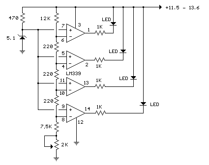
In the circuit below, a quad voltage comparator (LM339) is utilized as a simple bar graph meter to indicate the charge condition of a 12-volt lead-acid battery. A 5-volt reference voltage is connected to each of the positive inputs...
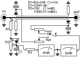
Many SWR (Standing Wave Ratio) and power meters used by amateur radio operators provide reasonably accurate continuous average power readings with a CW (Continuous Wave) key-down signal. However, these meters may not reliably measure Peak Envelope Power (PEP) or...
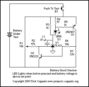
The Battery Good checker. When the button is pressed, the green LED will glow if the battery voltage is above the preset threshold. This version has a higher parts count than the Battery Low version, but a bonus is...