
Industrial fuel oil furnace controller circuit diagram 2
The industrial fuel oil furnace controller circuit is designed to manage the operation of a fuel oil furnace efficiently and reliably. The power supply circuit plays a crucial role in ensuring that the entire system receives stable voltage levels necessary for its operation. The step-down capacitor (C6) is used to reduce the voltage from the main supply to a level suitable for the circuit's components. Following the capacitor, the discharge resistor (R5) helps to safely dissipate any stored charge when the circuit is powered down, preventing potential damage to sensitive components.
The voltage regulator diode (VS1) is essential for maintaining a consistent output voltage, compensating for variations in the input voltage, and ensuring that the control circuits operate within their specified voltage range. The rectifier diode (VD) converts alternating current (AC) from the power supply into direct current (DC), which is critical for the operation of electronic components within the controller circuit. The filter capacitors (C1) are employed to smooth out any ripples in the DC output, providing a stable supply voltage to the subsequent control circuits.
The testing and ignition control circuit is responsible for initiating the combustion process in the furnace. This circuit typically includes components such as sensors to monitor the presence of fuel and air, as well as ignition elements that create the necessary spark to ignite the fuel. The control implementation circuit processes the signals from the testing and ignition control circuit and executes the necessary actions to maintain optimal furnace operation, including adjusting fuel flow rates and monitoring temperature levels.
Overall, the industrial fuel oil furnace controller circuit is a vital assembly that integrates several subsystems to ensure efficient and safe operation of the furnace. Each component within the circuit has a specific function that contributes to the overall performance and reliability of the heating system. Proper design and implementation of this circuit are critical for achieving efficient fuel consumption and maintaining safe operating conditions within the furnace.The industrial fuel oil furnace controller circuit is composed of the power supply circuit, testing and ignition control circuit and control implementation circuit, and it is shown as the chart. The power supply circuit is composed of the step-down capacitor C6, discharge resistor R5, voltage regulator diode VS1, rectifier diode VD and filter capacitors C1,..
🔗 External reference
Related Circuits
A new user has joined the forum and is seeking assistance with circuit design. They express a desire for guidance and acknowledge their inexperience in the subject. In circuit design, it is crucial to understand the fundamental components and their...
It is possible to add bus masters to the system, but a different bus architecture would be required since the Integrator/CP uses the AHB-Lite bus protocol, which allows only one bus master (the ARM CPU core). One way to...
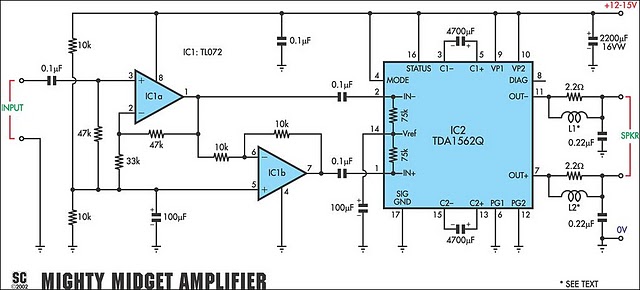
It is based on a Philips class-H audio amplifier IC and can deliver 36W RMS or 70W music power, all from a 13.8V supply. The Mighty Midget Amplifier can provide approximately 36W RMS continuous power into a 4-ohm load...
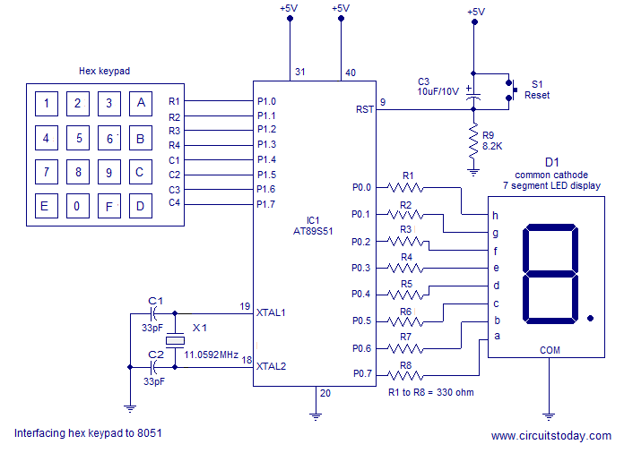
Interfacing a hex keypad to an 8051 microcontroller. The AT89S51 is utilized in this setup. A circuit diagram and assembly language program are included. A testing video is also provided. The interfacing of a hex keypad with the AT89S51 microcontroller...
Face Through attendance is the world's first embedded facial recognition machine, with an error rate of less than one in one hundred thousand and a rejection rate of less than one percent. In the field of biometrics, this device...
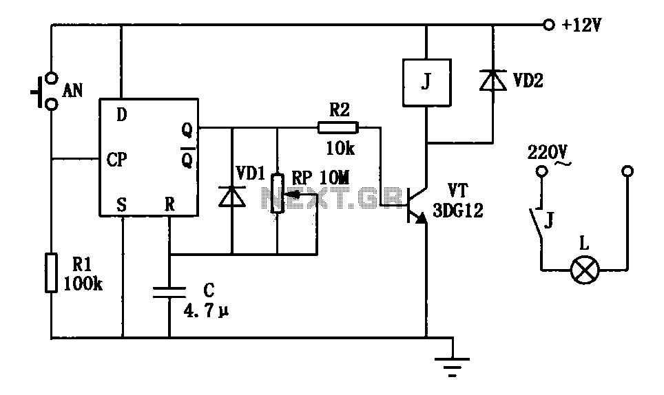
An exposure timer circuit is illustrated using D flip-flops, allowing for timing adjustments between 1 to 30 seconds. The D flip-flop circuit is connected to a one-shot timer. When exposure is required, pressing button AN generates a pulse that...