
Inexpensive_frequency_counter_tachometer
This circuit illustrates the configuration of an ICM7217 and an ICM7555 designed as a basic frequency counter. The connections between the ICM7217 and a common-cathode LED display are depicted in Figure 12-18. Calibration of the frequency counter is accomplished using resistor RA for coarse adjustment and resistor RB for fine adjustment. The ICM7555 timer is configured as an astable multivibrator.
The circuit utilizes the ICM7217, a digital frequency counter that counts the frequency of input signals and displays the result on a common-cathode LED display. The ICM7217 processes the incoming frequency signals and converts them into a digital format, which is then displayed visually. The common-cathode LED display is connected to the output pins of the ICM7217, allowing for straightforward reading of the frequency values.
The ICM7555 timer operates in an astable mode, generating a continuous square wave output that serves as a timing reference for the frequency counter. This configuration allows the circuit to measure frequencies accurately over a specified range. The astable multivibrator setup requires external resistors and capacitors to determine the frequency of oscillation, which can be adjusted to suit the application.
Calibration of the frequency counter is essential for accuracy. Resistor RA is utilized for coarse adjustments, enabling the user to make significant changes to the measurement range, while resistor RB allows for fine-tuning of the frequency reading. This dual control mechanism ensures that the circuit can be precisely calibrated against a known frequency standard, enhancing measurement reliability.
Overall, this circuit design effectively combines the capabilities of the ICM7217 and ICM7555 to create a functional and accurate frequency counter suitable for various electronic applications.This circuit shows an ICM7217 and an ICM7555 that are connected as a basic frequency counter. The connections between the ICM7217 and a common-cathode LED display are shown in Fig. 12-18. The frequency counter is calibrated (against a known standard) using RA as a coarse control and RB as a fine control.Notice that the ICM7555 timer is connected as an asta.. 🔗 External reference
Related Circuits
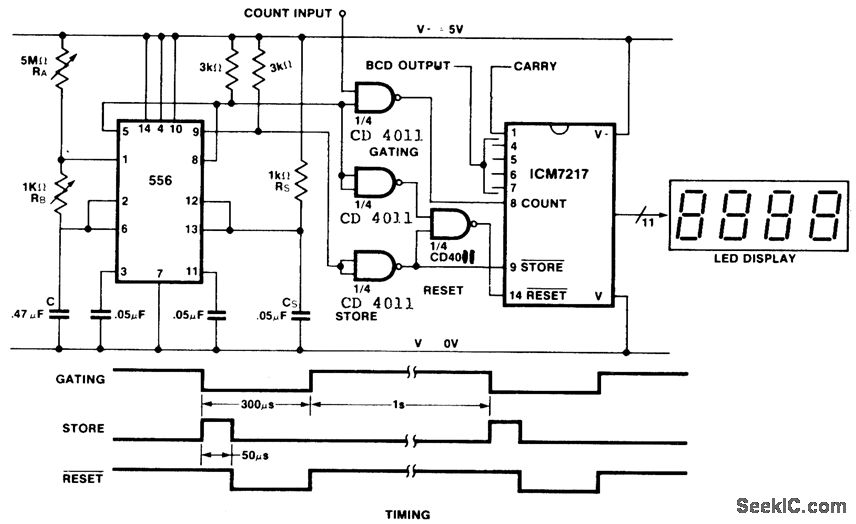
This is an inexpensive frequency counter and tachometer circuit. It utilizes a 556 dual timer to generate the gating, not-store, and not-reset signals for an ICM7217 counter. One timer operates as an astable multivibrator using resistors RA, RB, and...
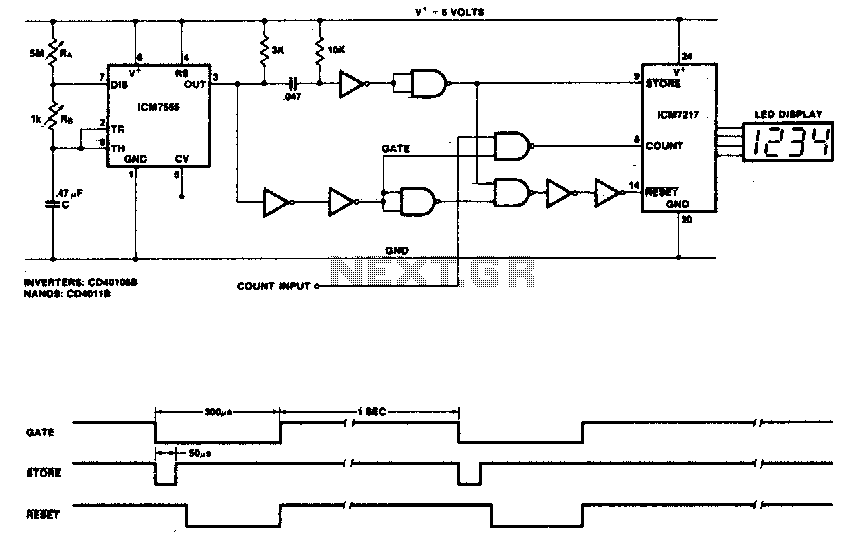
This circuit utilizes the low-power ICM7555 (CMOS 555) to generate the gating, STORE, and RESET signals. The timer is configured as an astable multivibrator to provide the gating signal. Calibration of the system is achieved using a 5 MΩ...