
Inexpensive frequency counter tachometer

The described frequency counter and tachometer circuit is designed to provide a cost-effective solution for measuring frequency and rotational speed. The core of the design employs the 556 dual timer IC, which integrates two timing circuits into a single package, allowing for compact construction and efficient performance.
The astable multivibrator configuration is established by selecting appropriate values for RA, RB, and C. In this configuration, the output oscillates between high and low states, generating a square wave signal. The duration of the high state is approximately 1 second, while the low state lasts between 300 to 500 microseconds. This timing is crucial as it defines the gating period for the ICM7217 counter, ensuring that the counter only registers input during the designated intervals.
Calibration of the circuit is facilitated by the inclusion of two potentiometers. The 5M potentiometer (RA) allows for coarse adjustments to the timing period, while the 1K potentiometer (RB) enables finer control. This dual-potentiometer setup provides the user with the flexibility to fine-tune the circuit for various applications, accommodating different frequency ranges and ensuring accurate measurements.
The second timer, configured as a one-shot multivibrator, is crucial for generating the store pulse. It is triggered by the negative edge of the gating signal, which ensures that the counter only captures the frequency data at the appropriate moment. The output from the one-shot is inverted, serving a dual purpose: it acts as the store pulse for the ICM7217 and keeps the not-reset signal in a high state. This prevents the counter from resetting until the one-shot has completed its timing cycle.
Once the one-shot times out, the store pulse transitions high, which in turn drives the not-reset signal low, effectively resetting the counter and preparing it for the next measurement cycle. The width of the one-shot pulse is approximately 50 microseconds, a critical parameter that must be adhered to for proper operation.
Attention to detail is imperative during the calibration process, particularly in ensuring that the gating low time is sufficiently longer than the one-shot pulse width. This precaution guarantees that the counter operates correctly, avoiding erroneous readings. Overall, this circuit represents an efficient and economical approach to frequency measurement, suitable for a variety of applications in electronics and engineering.Inexpensive frequency counter/tachometer. This circuit uses a 556 dual timer to generate the gating, not-store and not-reset signals for a ICM7217 counter. One timer is an astable multivibrator using RA, RB and C to provide an output that is positive for approximately 1 second and negative for approximately 300 to 500 s to serve as the gating si
gnal. The system is calibrated by using a 5M pot for RA as a coarse control and a 1 K pot for RB as a fine control. The other timer is a one-shot multivibrator triggered by the negative-going edge of the gating. This output at pin 9 is inverted to serve as the store pulse and to hold not-reset high. When the one-shot times out and the store goes high, not-reset goes low, resetting the counter. The one-shot pulse width is approximately 50 s with the components shown. When fine trimming with FIB care should be taken to keep the gating low time at least twice as long as the one-shot pulse width (courtesy Intersil, Inc.
). 🔗 External reference
Related Circuits
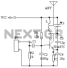
The ordinary triode 3DA87C is utilized to create a long-range FM transmitter circuit, which functions as a standard three-point oscillator circuit. This remote transmitter circuit is capable of large current emissions, achieving a range of up to 1 kilometer...
An equalizer is a passive or active electronic component or circuit, such as tone control, designed to modify or flatten the frequency response characteristics of a system. The NE5532 is a low-noise, dual operational amplifier that features full power...
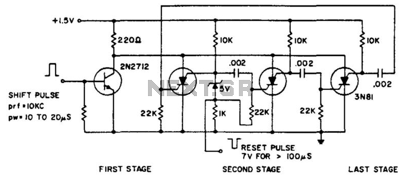
The ring counter operates from 1.0 to 6.0 V and requires only 6 mW at 1.5 V. The reset pulse activates the first stage with its trailing edge. The maximum shift pulse width increases with voltage and approaches 70...
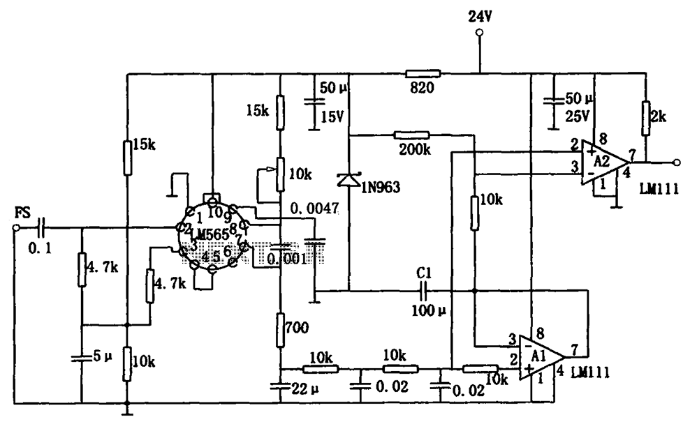
The sensitive frequency demodulation circuit utilizes the LM565 integrated circuit in a phase-locked configuration, allowing it to track frequency offsets across a wide range. However, at small frequency offsets, the signal can produce a minimal demodulated output, causing the...
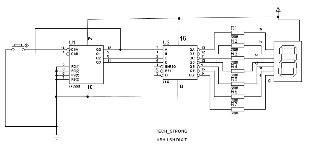
This project allows for the display of digits from 0 to 9 on a seven-segment display while counting the number of people entering a room. A counter IC, the 7490, is utilized alongside a BCD to seven-segment decoder IC,...
The attached schematic diagram is a Johnson Counter. Please provide advice on why "Loop 2" is considered to be invalid. Additionally, please suggest a few alternatives. The Johnson Counter, also known as a twisted ring counter, is a type of...