
Infrared intrusion barrier
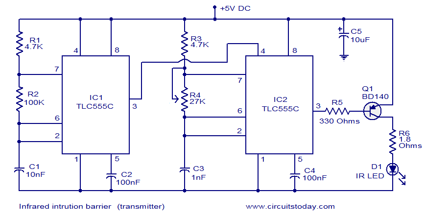
The infrared intrusion detector circuit operates on the principle of modulated infrared light transmission and reception. The transmitter section, utilizing two TLC555 timers, generates a modulated infrared signal. The first timer (IC1) operates in astable mode to create a low-frequency square wave at 300 Hz, which serves as a modulation signal for the second timer (IC2). This second timer, also in astable mode, produces a high-frequency square wave at 36 kHz, which is modulated by the 300 Hz signal from IC1. This modulation results in bursts of 36 kHz pulses with a duration of 3 ms, effectively encoding the signal for transmission.
The output from IC2 is fed into a transistor (Q1), which functions as a switch to control the infrared LED. When the circuit is active, the LED emits infrared light that forms an invisible barrier. The receiver section, comprising the TSOP1836 infrared receiver, detects this modulated infrared signal. In the absence of interruption, the TSOP1836 outputs a low signal, keeping the TLC555C timer from oscillating. The connection of the TSOP1836 output to the reset pin of the TLC555C ensures that the timer remains inactive as long as the infrared beam is intact.
Upon interruption of the infrared beam by a trespasser, the output of the TSOP1836 changes to high, triggering the TLC555C timer to start oscillating. This oscillation activates the piezo buzzer connected to the output of IC2, alerting to the presence of an intruder. The design emphasizes simplicity and effectiveness in detecting unauthorized access, making it suitable for various security applications. The circuit can be further refined by adjusting component values or adding features such as adjustable sensitivity or remote notification capabilities.Here is the circuit diagram of an infrared intrusion detector. Whenever a trespasser cuts the invisible infrared beam an alarm sound will be raised. The arrangement consists of a receiver circuit and a transmitter circuit. The transmitter circuit is based on two TLC555 ICs (IC1 and IC2). The first 555 (IC1) is wired as an astable multivibrator ope rating at 300Hz. The second 555(IC2) is also wired as an astable multivibrator operating at 36 KHz which can be adjusted by using POT R4. The output of IC1 is given to the reset pin of IC2. So the output of IC2 will be a burst of 36 KHz pulses modulated by a 300Hz signal. In simple words, the output will be a burst of 36KHz pulses with a spacing of 3mS in time. This signal is fed to the base of Q1 which drives the IR LED to transmit the waveform. The receiver stage is based on a TSOP1836 (IC1) IR receiver and a TLC555C timer IC1. When the IR signal is falling on the TSOP1836, its output will be low and this prevents the TLC555C from oscillating.
This is because the output of TSOP1836 is connected to the reset pin of TLC555C and this makes the reset pin low as long there is IR waveform falling on the receiver. When the IR waveform is cut by a passing intruder, output of IC1 goes high and makes the IC2 to start oscillation.
The piezo buzzer connected at the output of IC2 sound to indicate the intrusion. We aim to transmit more information by carrying articles. Please send us an E-mail to wanghuali@hqew. net within 15 days if we are involved in the problems of article content, copyright or other problems. We will delete it soon. 🔗 External reference
Related Circuits
Model Railroader is the world's largest magazine on model trains and model railroad layouts. It offers assistance for both beginners and advanced enthusiasts across all model railroading scales, including layout track plans, product reviews, news, and forums. Model Railroader magazine...

Infrared interruption counter is a reliable circuit that takes over the task of counting number of interruptions very accurately. When somebody enters into the room, then the Counter is Incremented by one. The total number of Persons inside the...
The diagram illustrates a human infrared remote sensing lamp circuit. It utilizes the trace infrared heat emitted by humans to control the lamp's operation, allowing it to turn on or off remotely. This human infrared remote sensing lamp features...
An infrared reflective burglar alarm utilizes infrared detection through reflective components, with a maximum detection range of up to 12 meters to trigger an alarm. When an intrusion is detected, a realistic barking sound is emitted to alert the...
This project allows for wireless transmission of audio from a television to headphones using infrared (IR) technology. It eliminates the need for physical connections between the TV and the headphones. Instead of traditional wiring, it employs infrared light to...
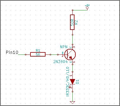
The 2N3904 is an NPN transistor. When observing the flat face of the transistor, the left lead is the Emitter (pin 1 in the schematic), the middle lead is the Base (pin 2 in the schematic), and the right...