
Infrared receiver
The circuit design integrates a phototransistor (Q1) that is sensitive to amplitude-modulated infrared light, allowing it to effectively detect signals transmitted via infrared communication. The phototransistor acts as a light-to-voltage converter, where the intensity of the incoming infrared light modulates the collector current, producing an electrical signal that can be further amplified.
The three-stage high-gain audio amplifier is essential for boosting the low-level signals generated by the phototransistor. This amplifier configuration typically includes multiple transistor stages, each providing additional gain while maintaining signal integrity. The use of a high-gain amplifier is crucial for ensuring that the output signal is strong enough to drive headphones or other audio output devices.
Transformer T1 plays a pivotal role in impedance matching, which is necessary for optimal power transfer between the amplifier and the load (headphones). Low-impedance headphones, which are commonly used today, require a specific output impedance from the amplifier to function effectively. The transformer is designed to step down the impedance from the amplifier to match the low-Z headphones, enhancing audio quality and preventing distortion.
In scenarios where high-impedance (high-Z) headphones are employed, the circuit can be modified by removing the transformer T1. High-Z headphones typically have a higher resistance (1000-2000 ohms) and can be directly connected to the circuit. This adjustment allows for a direct interface with the amplifier output, ensuring that the audio signal is delivered effectively without the need for impedance matching.
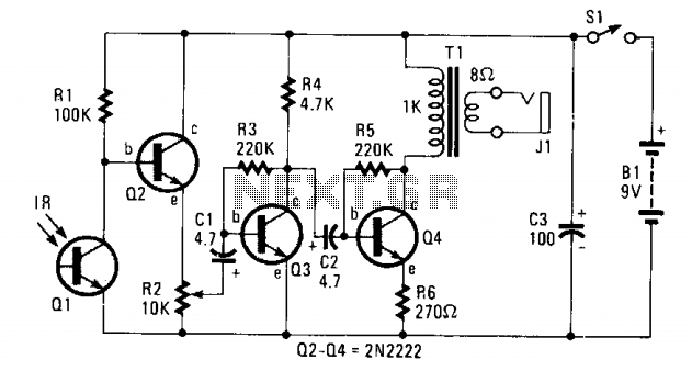
Overall, this circuit design provides flexibility in headphone compatibility, allowing users to choose between low-impedance and high-impedance options based on their preferences and equipment. The inclusion of a phototransistor and a high-gain amplifier ensures that the system can effectively process infrared signals and deliver high-quality audio output.The circuit consists of Ql—a phototransistor that responds to an intensity of amplitude-modulated IR light source—and a three-stage, high-gain audio amplifier. Transformer Tl is used to match the output impedance of the receiver to today's popular low-impedance (low-Z) headphones;
but if a set of 1000-2000 ohm, magnetic (not crystal), high-impedance (high-Z) phones are to be used, remove Tl and connect the high-Z phones in place of Tl's primary winding—the 1000-ohm winding. 🔗 External reference
Related Circuits
Model Railroader is the world's largest magazine on model trains and model railroad layouts. It offers assistance for both beginners and advanced enthusiasts across all model railroading scales, including layout track plans, product reviews, news, and forums. Model Railroader magazine...
The diagram illustrates a human infrared remote sensing lamp circuit. It utilizes the trace infrared heat emitted by humans to control the lamp's operation, allowing it to turn on or off remotely. This human infrared remote sensing lamp features...
This circuit enables the generation of audio musical notes that can be heard from a distance of up to 10 meters. It consists of two main components: an infrared (IR) music transmitter and an IR music receiver. The IR...
In the transmitter schematic, a ballast resistor is not depicted because most small laser power supplies are typically equipped with an integrated ballast resistor. However, variations in power supply designs may require the addition of an external resistor. In laser...
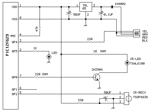
This unit uses one TSAL6100 IR/LED emitter from Digi-Key. This IR diode has a narrow (10 degree) radiation pattern at 940 NM. It is driven via 2n2904 transistor for maximum current pulses. The detector is a Vishay TSOP4838 38Khz...
This receiver is designed around the widely used ZN414 integrated circuit (IC) and operates within the AM band, covering frequencies from 550 to 1600 KHz. To utilize the receiver for Longwave frequencies, it is necessary to replace the coil...