
LASER Transmitter/Receiver

In laser applications, the ballast resistor plays a crucial role in stabilizing the current flowing through the laser diode. It ensures that the diode operates within its specified current range, preventing damage due to excessive current. The absence of a ballast resistor in the schematic indicates that the design assumes the presence of this component within the power supply circuit.
When designing or modifying a transmitter circuit, it is essential to verify the specifications of the power supply being used. If the power supply does not include a built-in ballast resistor, it is necessary to incorporate an external resistor to safeguard the laser diode. The value of the ballast resistor can be calculated based on the desired operating current of the laser diode and the voltage drop across the resistor.
Typically, the resistor value can be determined using Ohm's Law (V = I * R), where V is the voltage drop across the resistor, I is the desired current through the laser diode, and R is the resistance. It is advisable to select a resistor rated for sufficient power to handle the heat generated during operation.
In summary, while the schematic omits the ballast resistor due to the assumption of its presence in the power supply, careful consideration must be given to the specific requirements of the laser diode and the characteristics of the power supply to ensure reliable and safe operation.In the transmitter schematic, no ballast resistor is shown because most small LASER power supplies already have one built in. Yours may differ, and a resistor may be needed. 🔗 External reference
Related Circuits
The recent Epilog Laser Challenge on Instructables.com inspired the idea of constructing a low-cost CNC laser. The engraver offered as a prize has a retail price of approximately $8,000, resulting in a significant tax burden. It is believed that...
The OPT301 is housed in a TO-99 8-lead package, offering good sensitivity with a bandwidth limited to 4 kHz. Its peak response is in the infrared region at 750 nm, while sensitivity in the visible red spectrum at 670...
This circuit illustrates the TLV3702 Laser Pointer Sensor Circuit Diagram. Features include its application in starting a robot and its effective functionality for control purposes. The TLV3702 Laser Pointer Sensor Circuit utilizes the TLV3702 comparator to detect the presence of...

The circuit below is similar to the one above but can be used with a laser pointer to toggle the relay rather than a push button. The IR photo transistor Q1 (Radio Shack 276-145A) or similar is connected to...
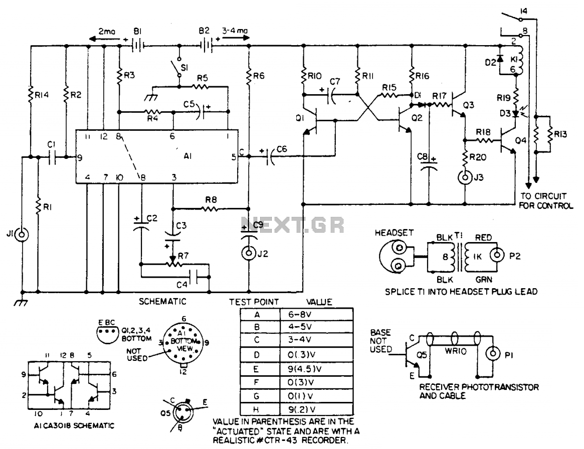
The laser light detector employs a sensitive phototransistor (Q5) positioned at the focal point of a lens (LE2). The output from Q5 is directed to a sensitive amplifier composed of an array (A1), which is biased through a voltage...
This chapter presents detailed schematics for various power supplies compatible with commonly available Ar/Kr ion tubes in the surplus market. It includes examples of commercial designs such as the Omnichrome 150R and 532 head, Lexel 88 and head, alongside...