
Infrared Transmitter-Receiver with 555

The infrared transmitter circuit is designed to modulate a carrier frequency that can be tuned with the R1 potentiometer. This allows for fine-tuning of the frequency, enhancing the ability of the receiver to detect the transmitted signal amidst potential interference from other infrared sources. The transmitter typically consists of a light-emitting diode (LED) that emits infrared light when energized, and the modulation ensures that the signal can be effectively captured by the receiver.
The receiver circuit includes a bandpass filter designed to isolate the frequency of interest while filtering out unwanted signals. This is achieved through the careful selection of L and C components, which set the resonant frequency of the filter. The operational amplifier plays a critical role in amplifying the filtered signal. The inclusion of diode D1 in the feedback loop is essential for rectifying low-level signals, allowing the circuit to operate effectively even with minimal input.
The comparator function of the final op-amp enables the detection of the received signal level against a set threshold. The R3 potentiometer allows for adjustment of this threshold, providing flexibility in the sensitivity of the receiver. This is particularly useful in environments with varying levels of ambient infrared noise. The power supply requirements of +12V for the op-amp and -12V for the potentiometer ensure that the circuit operates within its optimal range, facilitating reliable performance in remote control applications. Overall, this infrared transmitter and receiver circuit exemplifies a practical solution for wireless control systems, leveraging the principles of modulation, filtering, and signal amplification.Infrared transmitter and receiver circuit shown in the schematic diagram below can be used as remote control. The transmitter is basically an oscillator circuit, and the frequency can be adjusted using R1 potentiometer (or trimmer pot).
This oscillation makes sure if the signal can be distinguished from other source by the receiver. The receiver is actually a bandpass filter which filter out noise signal. The frequency of this filter is determined by L and C in the feedback path (from output to inverting input of the op-amp). D1 is inserted in the feedback path to enable rectifying very small signal, since the op-amp feedback mechanism will compensate the forward drop voltage of the diode.
The last op-amp is employed as a comparator, with the threshold is adjustable via R3 potentiometer. The op-amp should be supplied with + and 12Volt, and the R3 potentiometer should be supplied with -12V. [Circuit`s schematic diagram source: hobbyprojects. com] 🔗 External reference
Related Circuits
Pulse position modulation is similar to pulse width modulation, but the frequency is not constant. Like pulse width modulator circuit, pulse position modulation... Pulse Position Modulation (PPM) is a modulation technique in which the position of a pulse within a...
This is a simple yet effective darkness activator. It uses a light-dependent resistor (LDR) to detect light, and when no light is present, it activates an alarm from an 8-ohm speaker. The circuit can be easily modified to function...
This 555 timer circuit toggles a relay when a button is pressed. Pins 2 and 6, the threshold and trigger inputs, are held at half the supply voltage by two 10K resistors. When the output is high, the capacitor...
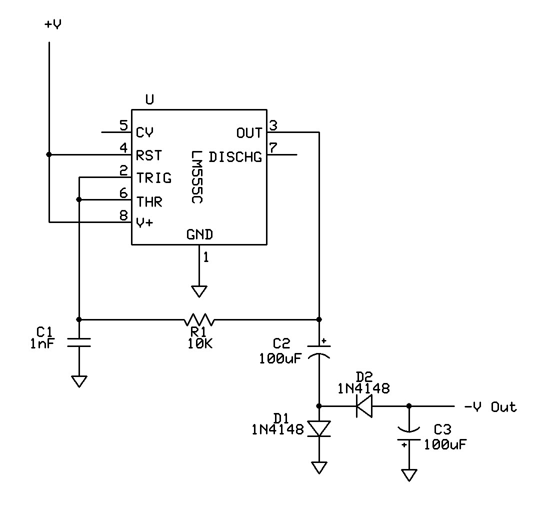
Can a 555 negative supply circuit, like the one below I pulled from another schematic, supply enough negative voltage to an LM324 and an AD736JN? The 555 timer integrated circuit can be configured to generate a negative voltage supply,...
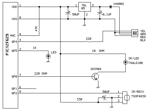
This unit uses one TSAL6100 IR/LED emitter from Digi-Key. This IR diode has a narrow (10 degree) radiation pattern at 940 NM. It is driven via 2n2904 transistor for maximum current pulses. The detector is a Vishay TSOP4838 38Khz...
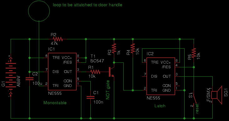
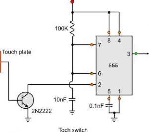
Security has become a significant concern in today's world, leading to the availability of various security gadgets. This document introduces a simple touch alarm designed specifically for doors with metallic handles. The alarm functions exclusively on metallic handles and...